Технология информационного моделирования
Описание принципа работы
Объект «Второй главный путь на перегоне Ния — Таковка Восточно-Сибирской железной дороги» включён в перечень пилотных проектов с использованием технологии информационного моделирования.
Генеральным директором — председателем правления ОАО «РЖД» — утверждена Дорожная карта от 7 июня 2021 г. № 938 по реализации на Восточном полигоне пилотных проектов с использованием технологии информационного моделирования.
Проектный институт «Иркутскжелдорпроект» представил по объекту сформированную информационную модель на этапе выполнения инженерных изысканий, на этапе осуществления архитектурно-строительного проектирования и аналитический отчёт по результатам подготовки проектной документации также в форме информационной модели.
Информационная модель была рассмотрена на предмет достаточности. По результатам проведения государственной экспертизы получено положительное заключение. Разработан, рассмотрен и согласован проект производства работ.
В настоящее время по объекту ведутся строительно-монтажные работы. Открытие движения запланировано на 2024 год.
Устройство закрепления (заграждения) составов УЗС
Описание принципа работы
Предназначено для закрепления составов на приёмоотправочных станционных путях, а также для остановки и удержания движущихся вагонов (составов) на сортировочных и сортировочно-отправочных путях с целью предупреждения их несанкционированного выхода за пределы сортировочного парка или приёмоотправочных путей.
Эффекты от внедрения
Применение пневматического силового привода обеспечивает широкую применяемость установки изделия в условиях холодного климата, а также простоту монтажа и обслуживания.
Использование железобетонных плит основания обеспечивает достаточную долговечность устройства. Также повышается ремонтопригодность устройства за счёт упрощения замены вышедших из строя элементов тормозной системы или замены секции устройства в сборе без демонтажа основания.
Ключевые моменты
Главная задача устройства УЗС — повышение уровня безопасности движения, вывод обслуживающего персонала из опасной зоны и исключение ручного труда.
Многофункциональное гидромеханическое оборудование УПТО РОИНТ
Описание принципа работы
Для нужд Центральной дирекции инфраструктуры в 2020 году в границах Дальневосточной железной дороги поставлено три единицы многофункционального гидромеханического оборудования УПТО РОИН на базе КАМАЗ и пять единиц на базе железнодорожной платформы.
В 2022 году в границах Забайкальской железной дороги поставлена одна единица оборудования УПТО РОИН на базе железнодорожной платформы и две единицы оборудования УПТО РОИН на базе КАМАЗ.
Оборудование предназначено для эксплуатации в путевом хозяйстве ОАО «РЖД» при проведении текущего и капитального ремонта железнодорожного пути и объектов инфраструктуры, в том числе для выполнения программ по ремонту земляного полотна и приведения полосы отвода дирекций инфраструктуры к нормативному состоянию с привлечением высокотехнологичной техники, а также для выполнения операций грузоподъёмных, экскаваторных и прочих работ с применением широкого спектра навесного оборудования.
Эффекты от внедрения
Для определения эффективности производства рассмотрим сравнительный анализ выполнения данных работ, выполненных ручным трудом.
1. Очистка русел ИССО
Общий годовой план работ — 905 м³
Согласно ТНК № 7.16 «Очистка от наносов русел малых мостов и труб с отвозкой грунта тачками», работа производится двумя монтёрами пути II разряда, норма времени составляет 2,52 человеко-часа на 1 м³. Норма на весь объём составит 905 м³ × 2,52 человеко-часа = 2 280,6 человеко-часа, что потребовало бы укомплектования штата дополнительно одним человеком.
Затраты на оплату труда (ФОТ + ЕСН) монтёров II разряда: 2280,6 человеко-часа × 75,14 руб. + 30,4 % (ЕСН) = 223 459 руб. (без учёта премии, зональной надбавки и выплат за вредные условия труда).
2. Планировка, разработка водоотводных канав
Общий годовой план работ — 50 м³, или 344 621,7 пог. м
Согласно ТНК № 7.12 «Очистка нагорных канав», работа производится монтёром пути II разряда (один человек), норма времени составляет 0,79 человеко-часа на 1 пог. м. Норма на весь объём составит 344 621,7 пог.м × 0,79 человеко-часа = 272 251,14 человеко-часа, что потребовало бы укомплектования штата дирекции ещё 138 работниками.
Затраты на оплату труда (ФОТ + ЕСН) монтёров пути II разряда: 272 251,14 человеко-часа × 75,14 руб. + 30,4 % (ЕСН) = 26 675 863,7 руб. (без учёта премии, зональной надбавки и выплат за вредные условия труда).
3. Очистка переездов от снега и наледи
Годовой план — 3 600 м³, 101 переезд
Согласно ТНК № 9 «Очистка переездов от снега и наледи», работа производится двумя монтёрами пути II разряда, норма времени составляет 9,82 человеко-часа на 1 переезд. Норма на весь объём составит 9,82 человеко-часа × 101 переезд = 991,82 человеко-часа, что потребовало бы укомплектование штата дирекции ещё одним работником.
Затраты на оплату труда (ФОТ + ЕСН) монтёров пути II разряда:
9,82 человеко-часа × 75,14 руб. + 30,4 % (ЕСН) = 962,19 руб. (без учёта премии, зональной надбавки и выплат за вредные условия труда).
Таким образом, затраты по оплате труда на производство работ ручным способом составили бы 29,9 млн руб. в год. С учётом средней премии 85,4 %, вредности 4 % затраты на оплату труда составили бы не менее 56,6 млн руб. в год.
Ключевые моменты
При эксплуатации тяжёлой техники при производстве вышеуказанных работ будут понесены следующие затраты:
Амортизация поступившей техники. При сроке полезного использования в среднем 85 месяцев годовые амортизационные отчисления составят 15,5 млн рублей (стоимость приобретения 110 млн рублей / 85 месяцев × 12 месяцев).
Затраты на топливо. Средний расход топлива в месяц — 6,9 т на 3 ед., средняя цена дизельного топлива — 46 875 рублей за 1 т. Затраты на топливо составят: 6,9 т × 46 875 рублей × 12 месяцев / 1 000 000 = 3,9 млн рублей в год.
Оплата труда. Дополнительный фонд заработной платы для содержания работников в количестве шести человек составит 4,7 млн рублей в год. Отчисления на социальные нужды — 30,4 % — 1,4 млн рублей. Прочие затраты на оплату труда (НПФ, ДМС, ВСХ и др.) составят 0,5 млн рублей.
Материалы. Затраты на специальную одежду работникам и содержание техники составят 0,4 млн рублей.
Прочие расходы. Затраты на медицинское освидетельствование, страхование имущества и разъездные составят 0,8 млн рублей.
Итого затраты составят: 15,5 + 3,9 + 4,7 + 1,4 + 0,5 + 0,4 + 0,8 = 27,2 млн рублей.
Минимальный экономический эффект: 56,6 – 27,2 = 29,4 млн рублей.
В состав одного комплекта оборудования входит:
Универсальное подъемно-транспортное оборудование (УПТО) — 1 ед.
Оборудование специальное навесное:
захват для шпал — 1 ед.
рельсовый захват — 1 ед.
грейфер для снега — 1 ед.
грейфер для вырезки щебня из шпальных ящиков и замены шпал — 1 ед.
трапециевидный ковш — 1 ед.
ковш общеземельный — 1 ед.
ковш планировочный — 1 ед.
грейфер копающий (с зубьями) — 1 ед.
молот гидравлический высокочастотный — 1 ед.
мульчер — 1 ед.
крюковая подвеска — 1 ед.
гидравлический захват — 1 ед.
бетоносмеситель — 1 ед.
люлька монтажная — 1 ед.
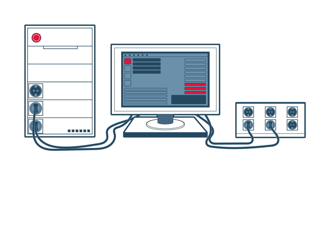
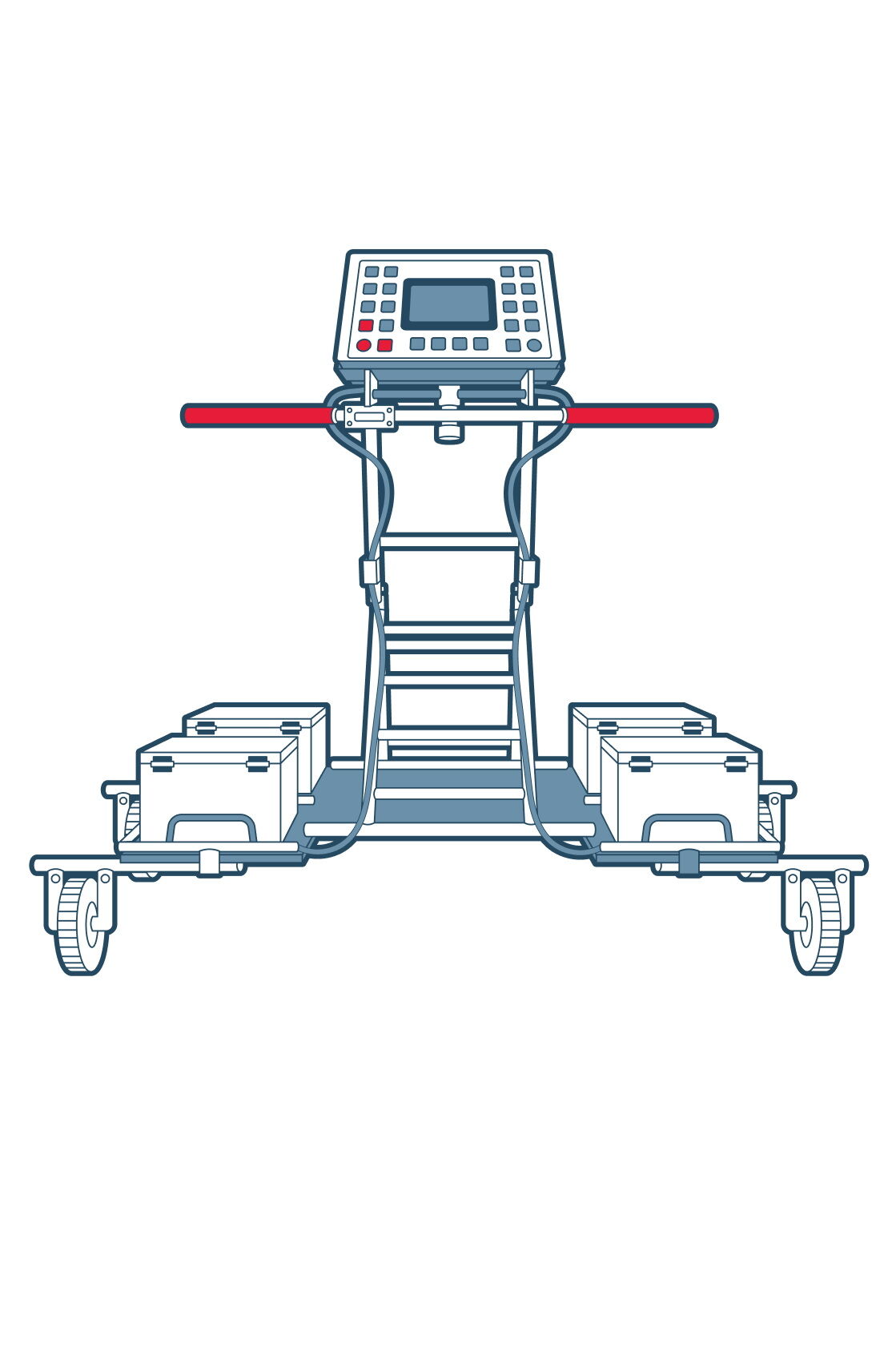
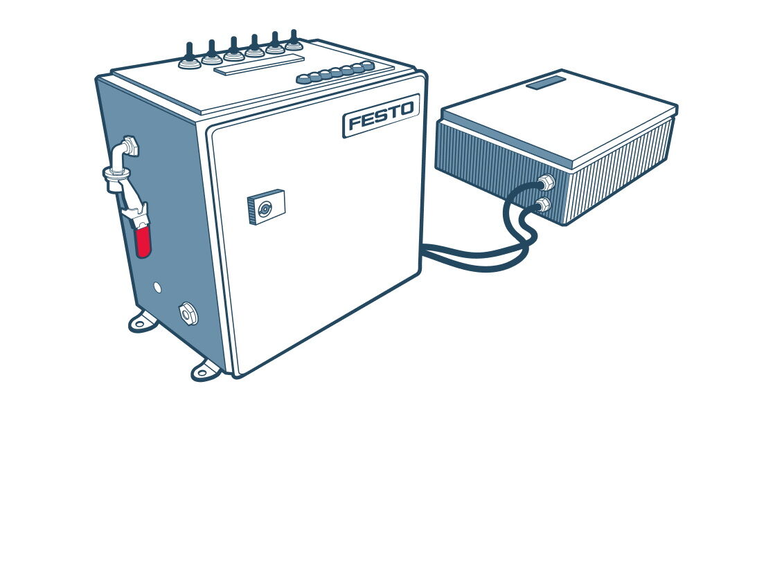
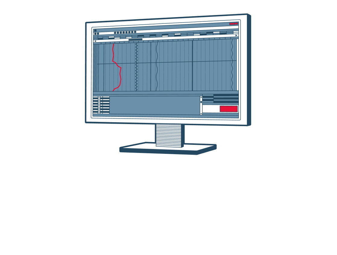
Технологический стенд СПБ-02
Описание принципа работы
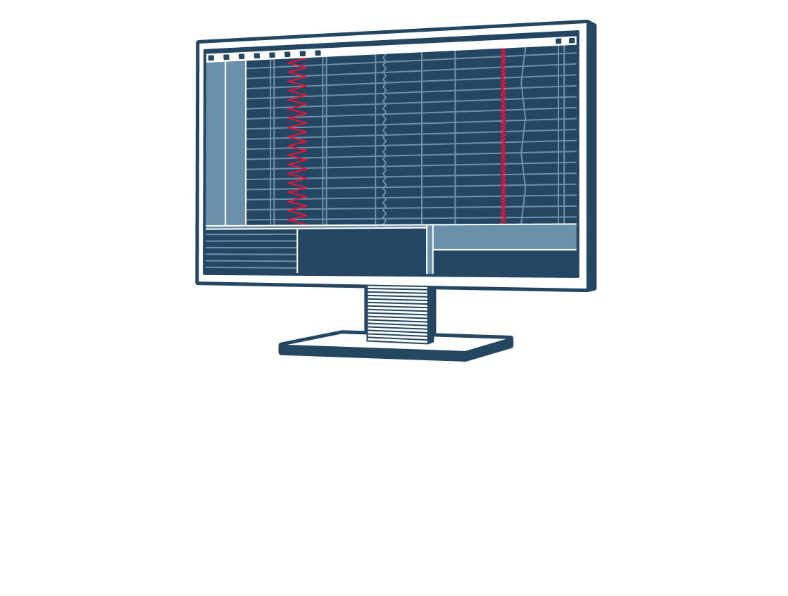
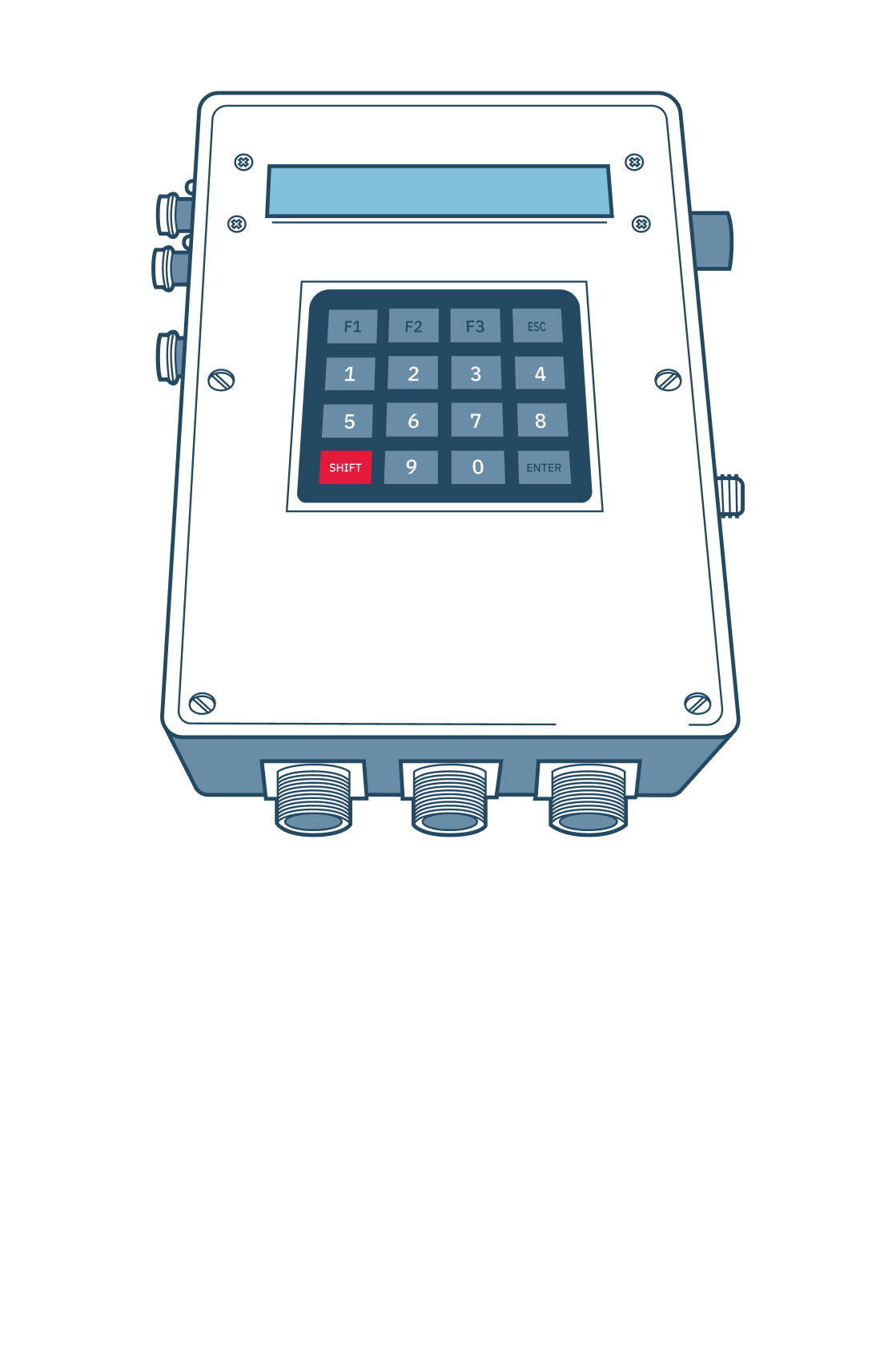
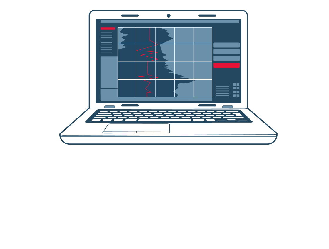
Технологический стенд СПБ-02 предназначен для автоматизированной проверки работоспособности, выявления неисправностей при проведении технического обслуживания и ремонтных работ оборудования систем автоведения и регистрации параметров движения локомотивов. Стенд представляет собой электронное устройство, в состав которого входит персональный компьютер со специальным программным обеспечением. Испытуемые электронные блоки систем автоведения и регистрации параметров автономно подключаются к стенду с помощью кабельного комплекта, входящего в состав стенда, и проверяются на работоспособность.
Эффекты от внедрения
Автоматическая проверка работоспособности тестируемых электронных блоков и соответствия их параметров требованиям ТУ (потребляемая мощность, вырабатываемые выходные напряжения, входные сопротивления измерительных каналов и т. д.).
Проверка всех интерфейсов связи, входящих в состав испытываемого оборудования (CAN, RS-485 и т. д.). Стенд имитирует внешние устройства, с которыми производится обмен информацией блоков в ручном режиме, и осуществляет поэтапную проверку работоспособности электронных узлов.
Ключевые моменты
Стенд позволяет программировать микроконтроллеры блоков с помощью встроенных программаторов по интерфейсам CAN и BDM, а также формирует отчёты с занесением в них результатов тестирования и сохраняет полученные отчёты на информационных носителях (жёсткий диск компьютера, принтер и пр.).
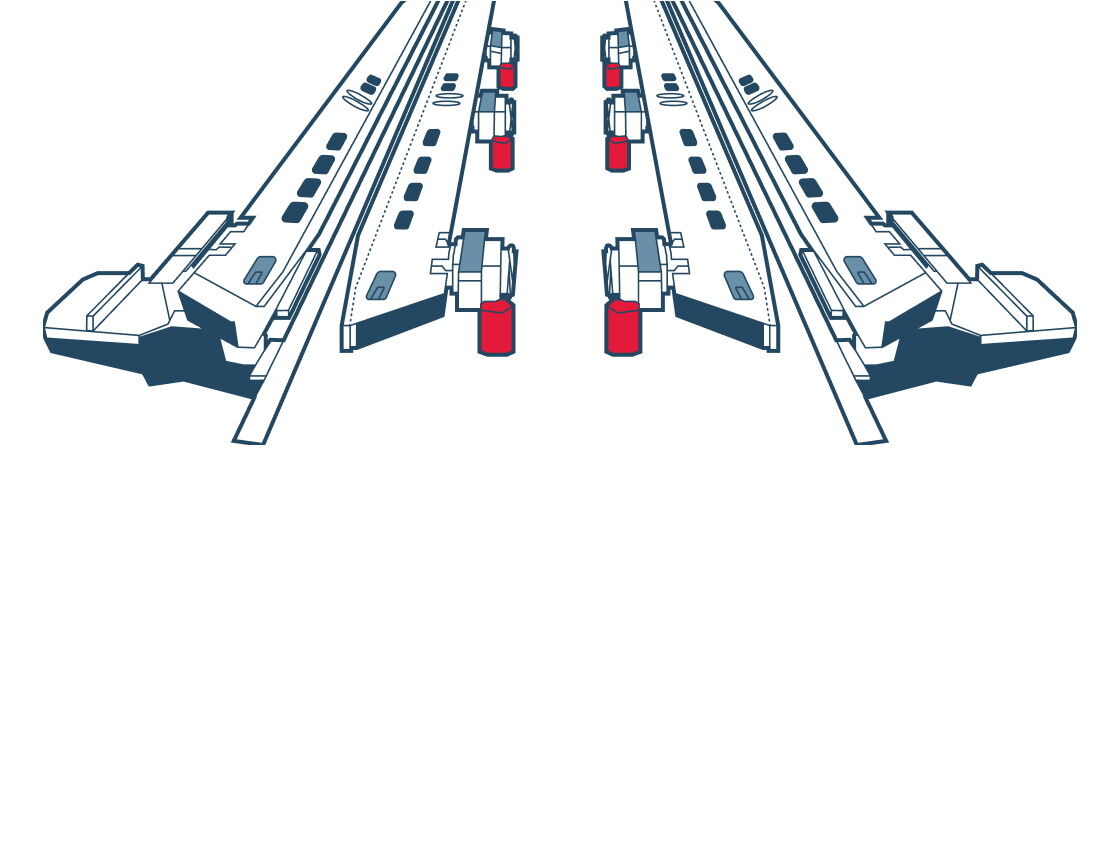
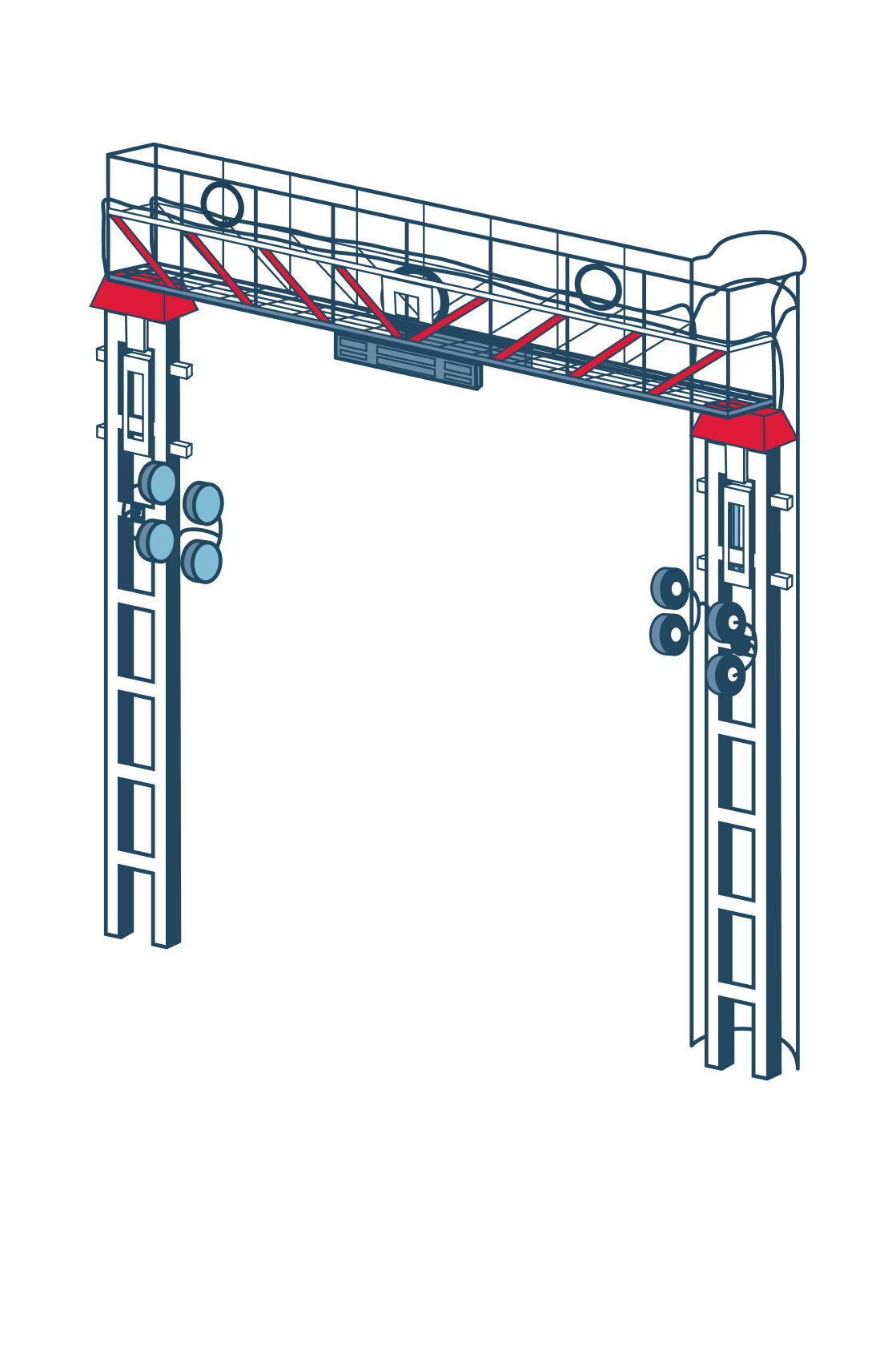
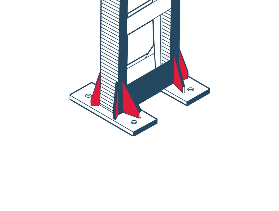
Нажимной вагонный замедлитель пневматический универсальный НЗПУ
Описание принципа работы
Предназначен для использования на прямых участках путей горочных и парковых тормозных позиций автоматизированных и механизированных сортировочных горок, находящихся в эксплуатации, а также проектируемых и сооружаемых вновь. При разработке был учтён многолетний опыт работы с замедлителями и рекомендации обслуживающего персонала сортировочных станций. В результате НЗПУ вобрал в себя все передовые технические новшества и является самым передовым замедлителем в Российской Федерации и за её пределами.
Эффекты от внедрения
Конструкция вагонного замедлителя допускает свободный проезд тепловозов любых модификаций.
Использование железобетонных плит основания обеспечивает долговечность конструкции. Повышается ремонтопригодность замедлителя за счёт упрощения замены вышедших из строя элементов тормозной системы или замены тормозной секции замедлителя в сборе без демонтажа основания.
Наличие легкосъёмного защитного кожуха предотвращает негативные внешние воздействия окружающей среды, а также исключает случайный контакт работника с движущимися элементами замедлителя, что повышает безопасность и снижает травматизм.
Наличие системы обдува позволяет значительно упростить очистку замедлителя от снега в зимний период.
Наличие несмазываемых элементов облегчает периодическое обслуживание замедлителя.
Конструкция рычагов и их расположение по длине замедлителя обеспечивает равномерное распределение тормозного усилия, повышает тормозную мощность при значительном снижении уровня шума.
Система предупреждения износа тормозных шин облегчает контроль их критического износа при настройке и регулировке.
Виртуальная сцепка (система ИСАВП-РТ-М)
Описание принципа работы
При вождении поездов по технологии «Виртуальная сцепка» между локомотивами по радиоканалу устанавливается соединение и осуществляется непрерывный обмен данными (место нахождения, длина, вес, текущий и перспективный режимы работы). Ведомый локомотив, идущий в попутном следовании, обрабатывает информацию с ведущего локомотива и выбирает оптимальный режим работы.
Модернизированная система УСАВП с установленной системой ИСАВП-РТ-М ведомого поезда, основываясь на информации от ведущего поезда, производит расчёт момента изменения сигнала огня локомотивного светофора с «жёлтого» на «зелёный» или с «красно-жёлтого» на «жёлтый», тем самым соблюдая наименьшее безопасное расстояние между ведущим и ведомым поездами без применения торможения и не нарушая скоростей движения, установленных устройствами безопасности. Для расчёта оптимальной траектории ведения поезда непрерывно производится расчёт эффективности работы системы торможения как своего состава, так и виртуально сопряжённого.
Эффекты от внедрения
Повышение безопасности движения.
Рост пропускной способности на существующей инфраструктуре до 15 %.
Возможный интервал движения между грузовыми поездами от 7 минут.
Сокращение оборота парка локомотивов до 20 %.
Ключевые моменты
Организация пакета до пяти локомотивов, работающих по технологии «Виртуальная сцепка».
Организация сетей радиообмена внутри пакета локомотивов, работающих по технологии «Виртуальная сцепка» за счёт встроенного приёмника сигналов спутниковой навигации.
Вождение пакетов в период работы «окон».
Выявление на борту локомотива предотказных состояний узлов и агрегатов.
Повышение коэффициента технической готовности локомотива без дополнительной предрейсовой диагностики за счёт формирования статистически значимых массивов данных о работе локомотива.
Улучшение энергообеспечения поездок за счёт накопления привязанных к пути данных о напряжении в контактной сети и потребляемом токе локомотива.
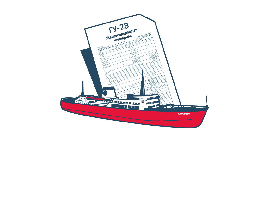
Цифровой приёмосдатчик (ДТЦФТО)
Описание принципа работы
В 2023 году, в рамках мероприятий по вывозу контейнеров с Дальнего Востока, Дальневосточным территориальным центром фирменного транспортного обслуживания предложена к реализации технология «Цифровой приёмосдатчик» для приёма к перевозке вагонов открытого типа, погруженных контейнерами.
Эффекты от внедрения
В период с 18 января по 30 июня 2023 года указанными грузоотправителями погружено 10 933 вагона с контейнерами, принято к перевозке в рамках действия технологии 8 084 вагонов, что составляет 74 % от общего количества погруженных вагонов.
Ключевые моменты
Проект вошёл в перечень инновационных, предлагаемых к реализации на полигоне Дальневосточной железной дороги в 2023 году, требующих установления экспериментального нормативного режима (ЭНР) согласно распоряжению ОАО «РЖД» № 2844 от 1 ноября 2022 года.
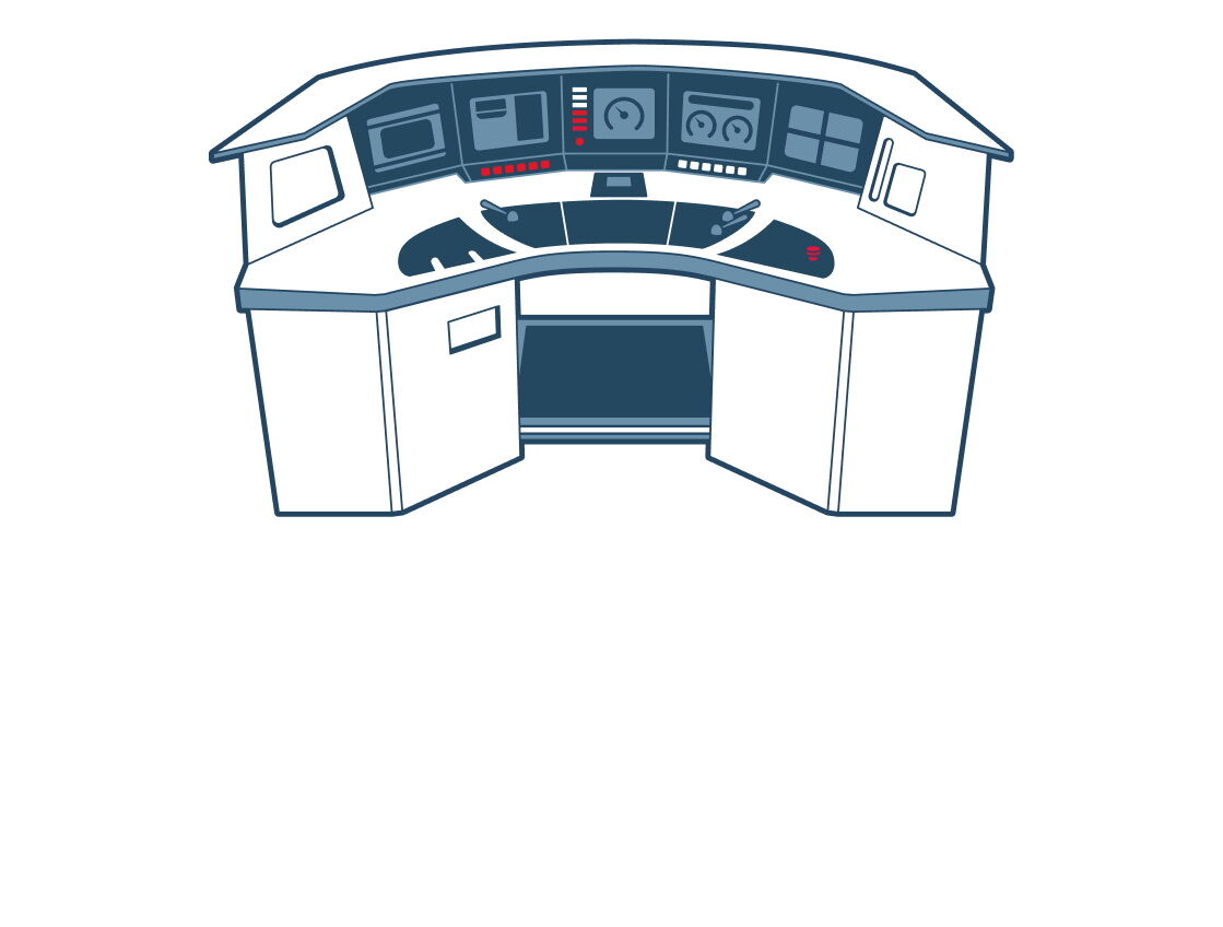
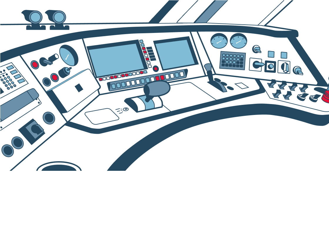
Новейший комплекс УПУ-4 (Унифицированный Пульт Управления)
Описание принципа работы
Изначально в концепцию разработки пульта машиниста УПУ закладывался принцип открытой архитектуры с возможностью за счёт программного обеспечения осуществлять стыковку аппаратуры пульта с существующими и перспективными системами управления, диагностики и обеспечения безопасности электропоезда. Таким образом, и сегодня сохраняется возможность доработки программного обеспечения и согласования видеокадров интерфейса диалога «Машинист — Электропоезд», обеспечивающая интеграцию практически любых цифровых систем в состав комплекса.
Эффекты от внедрения
Возможно использование в различных видах моторвагонного подвижного состава и локомотивах.
Предусмотрена модульность компонентов, что позволяет производить оперативный ремонт путём замены модулей.
УПУ содержит все необходимые компоненты для управления и диагностики систем поезда, а также системы, обеспечивающие транспортную безопасность (систему видеонаблюдения, пожарно-охранную сигнализацию, систему информирования пассажиров и систему подсчёта пассажиропотока).
Все системы комплекса тесно интегрированы с центральным вычислителем, что позволяет реализовать сложные взаимосвязанные алгоритмы управления и диагностики поезда.
Рабочее место имеет модульную конструкцию, что позволяет адаптировать его под разные конфигурации кабины подвижного состава, в т.ч. под управление в «одно лицо».
Имеется возможность конфигурирования пульта машиниста для ведения поезда без помощника.
Многофункциональные дисплеи имеют возможность переключения режимов отображения (режимы движения, диагностики, видеонаблюдения).
Дисплей машиниста имеет функцию автоматического переключения на камеры наблюдения за посадкой и высадкой при остановке на остановочном пункте.
Кнопки и тумблеры заменены на мембранные кнопки с функциональной подсветкой. Оптимизировано количество и расположение кнопок, панели выполнены в едином стиле.
Комплекс оснащён системой «технического зрения», которая использует изображение со штатных курсовых камер из состава системы видеонаблюдения и на основании обработки изображения искусственным интеллектом позволяет в реальном времени распознавать помехи на путях и предупреждать об этом машиниста.
Может быть оснащен проекционным дисплеем, обеспечивающим вывод на лобовое стекло основной информации, связанной с безопасностью движения.
Предусмотрен лазерный измеритель скорости, позволяющий избежать ошибок, связанных с погрешностями измерения скорости по колесу (неточно измеренный бандаж, проскальзывание колёсных пар, неравномерность вращения в кривых).
Используется производительная скоростная поездная шина на базе технологии Ethernet, которая позволяет синхронно и с высокой скоростью передавать сигналы управления на поездное оборудование, а также получать диагностические параметры. Поездная шина имеет резервирование.
Унифицированные вагонные адаптеры имеют широкий набор цифровых интерфейсов, позволяющих стыковаться с любым интеллектуальным вагонным оборудованием.
Высокий уровень автоматизации процессов управления оборудованием поезда обеспечивает комфортный диалог «человек — машина» и сводит к минимуму нагрузку на машиниста, а также позволяет гибко адаптировать работу системы управления под новые задачи без изменения аппаратной части.
Ключевые моменты
Размещение всех органов управления на столешнице и панелях пульта.
Интеграция в одном пульте с едиными решениями управления всех систем управления, диагностики и взаимодействия машиниста с аппаратурой электропоезда и обратной связи от систем электропоезда к машинисту.
Органы управления и средства отображения информации объединены в группы с учётом их функциональной и оперативной значимости.
Компоновка органов управления и средств отображения информации пульта машиниста выполнена с учётом современных тенденций и эргономических требований (компоновка информационной и моторной панели пульта управления машиниста с разграничением на зоны тяги, торможения, аварийной сигнализации и вспомогательных переключений).
Неразрушающий контроль рельсов
Описание принципа работы
Основное и в ряде случаев единственно возможное средство предотвращения чрезвычайных ситуаций на железнодорожном транспорте, возникающих из-за изломов рельсов по причине образования в них дефектов. Для их своевременного выявления используются съёмные и мобильные средства ультразвукового (УЗ) контроля.
Эффекты от внедрения
Предотвращение чрезвычайных ситуаций на железнодорожном транспорте из-за изломов рельсов по причине образования в них дефектов.
Ключевые моменты
Неразрушающий контроль рельсов выполняется с установленной периодичностью (Распоряжением ОАО «РЖД» от 26 июля 2017 г. № 1471р). Для контроля рельсов применяются мобильные средства дефектоскопии (вагоны дефектоскопы, дефектоскопные автомотрисы). Контроль осуществляется экипажем мобильного средства, съёмными средствами дефектоскопии (дефектоскопными тележками) и оператором дефектоскопа.
Системами рельсовой дефектоскопии выявляются:
- расслоения и поперечные трещины в головке рельса
- продольные трещины в местах сопряжения головки с шейкой рельса
- трещины, развивающиеся от болтовых отверстий
- продольные и поперечные трещины в шейке и подошве рельса
- дефекты в сварных стыках рельсов
Система неразрушающего контроля рельсов выполнена по принципу ультразвуковой дефектоскопии. Дополнительно могут использоваться магнитные каналы для контроля поверхностных дефектов (перечень дефектов установлен Распоряжением ОАО «РЖД» от 23 октября 2014 г. № 2499р).
Техническая информация
Скорость контроля мобильными средствами дефектоскопии
до 120 км/ч
Скорость контроля съёмными средствами дефектоскопии
до 6 км/ч
Виды каналов
ультразвуковые, магнитные
Диапазон регулировки коэффициента усиления ультразвуковых каналов
0–96 дБ
Шаг прозвучивания поперечных сечений рельса
до 5 мм
Достоверность выявления дефектов
не менее 95%
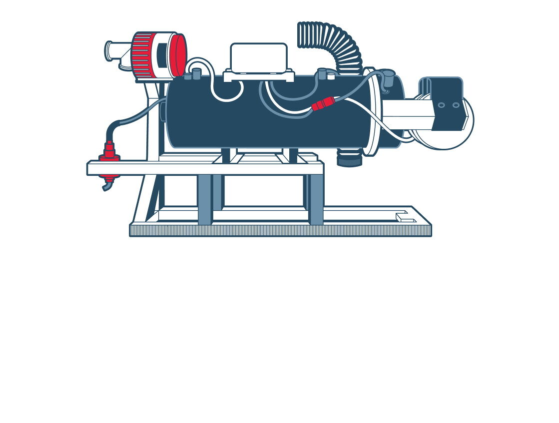
Автоматизированная система прогрева тепловоза АСПТ «Локотерм»
Описание принципа работы
Предназначена для поддержания температур теплоносителей неработающего дизеля маневрового и магистрального тепловоза на уровне, обеспечивающем его надёжный запуск в условиях низких температур окружающего воздуха.
Эффекты от внедрения
Прогрев теплоносителей в масляной и водяной системах тепловоза и подогрев кабины машиниста при заглушённом дизель-генераторе.
Передача sms-сообщений с данными о состоянии системы по каналу GSM.
Определение географических координат местоположения тепловоза.
Повышение точности планирования и учёта расхода топлива.
Проведение анализа работы и учёта расхода топлива благодаря интеграции с системой регистратора параметров движения тепловоза РПДА-Т по CAN-интерфейсу, которая исключает дублирование одинаковых блоков и датчиков.
Ключевые моменты
Поддержание в автоматизированном режиме рабочей температуры при наружных температурах до −50 °С:
— охлаждающей жидкости в диапазоне от +20 до +80 °С;
— масла в диапазоне от +20 до +50 °С;
— воздуха в кабине машиниста в диапазоне от +5 до +30 °С;
— топлива в баке тепловоза в диапазоне от 0 до +7 °С.
Выдача сообщений о возникших нарушениях в функционировании системы ответственным лицам по каналу GSM.
Техническая информация
Теплопроизводительность в режиме «полный»
60 кВт
Теплопроизводительность в режиме «малый»
14 кВт
Номинальное напряжение питания
24 В
Расход топлива в режиме «полный»
8 л/ч
Расход топлива в режиме «малый»
1,8 л/ч
Время работы
не менее 10 ч
Теплопроизводительность в режиме «полный»
4 кВт
Теплопроизводительность в режиме «малый»
1 кВт
Номинальное напряжение питания
4 В
Расход топлива в режиме «полный»
0,49 л/ч
Расход топлива в режиме «малый»
0,12 л/ч
Время работы
не менее 10 ч
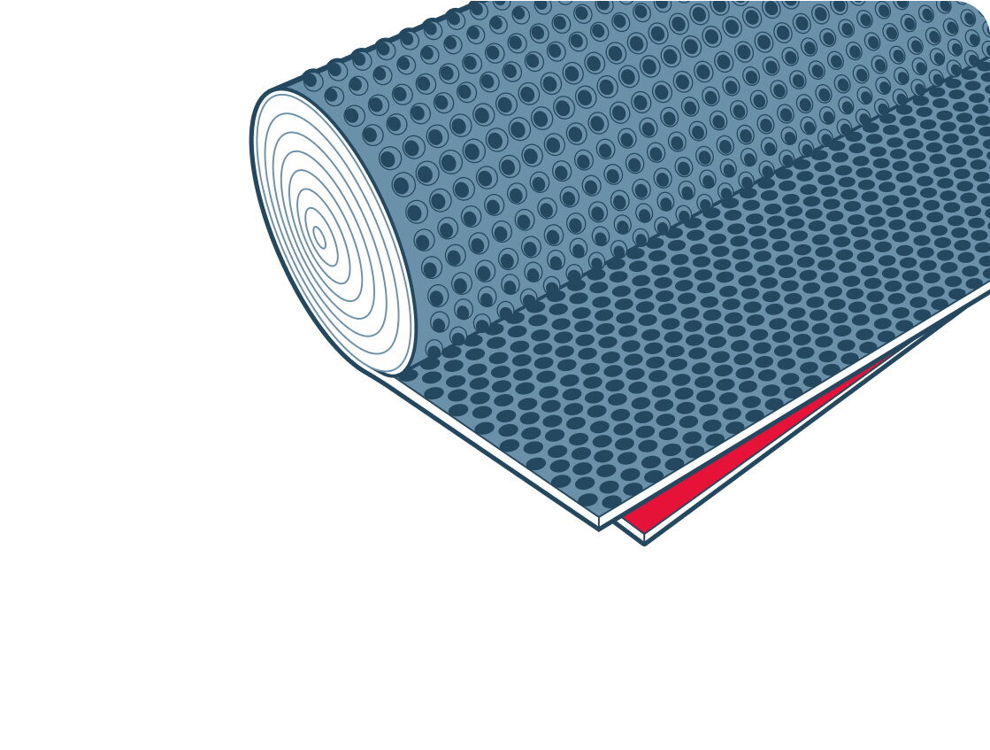
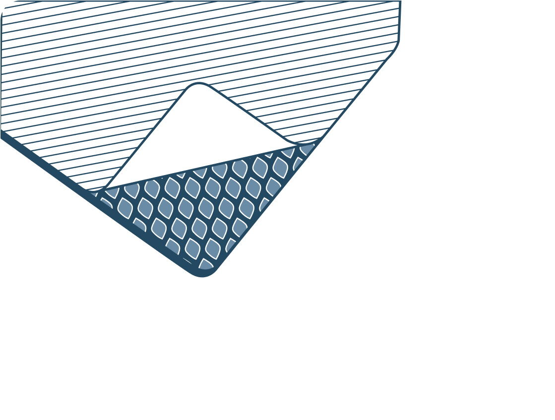
Геомембрана «ТЕФОНД»
Описание принципа работы
Используемый для производства геомембран полиэтилен отличается превосходной прочностью и стойкостью к воздействию различных химических веществ (например, гуминовой кислоты, которая содержится в почве, или растворам кислот и щелочей, содержащихся в грунтовых водах). Имеющиеся на поверхности материала выступы создают хорошие условия для дренажа и вентиляции, предотвращают выпадение конденсатов.
Эффекты от внедрения
Исключение проникновения загрязнённых вод с балластной призмы и земляного полотна в композитный лоток и далее на очистные сооружения поверхностных сточных вод.
Ключевые моменты
Локации применения: железнодорожная инфраструктура на участке Лена-Восточная — Таксимо Восточно-Сибирской железной дороги.
Наименование объекта: Строительство двухпутной вставки на перегоне Тыя — Северобайкальск (земляное полотно).
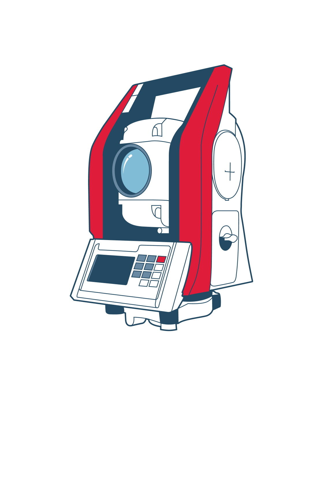
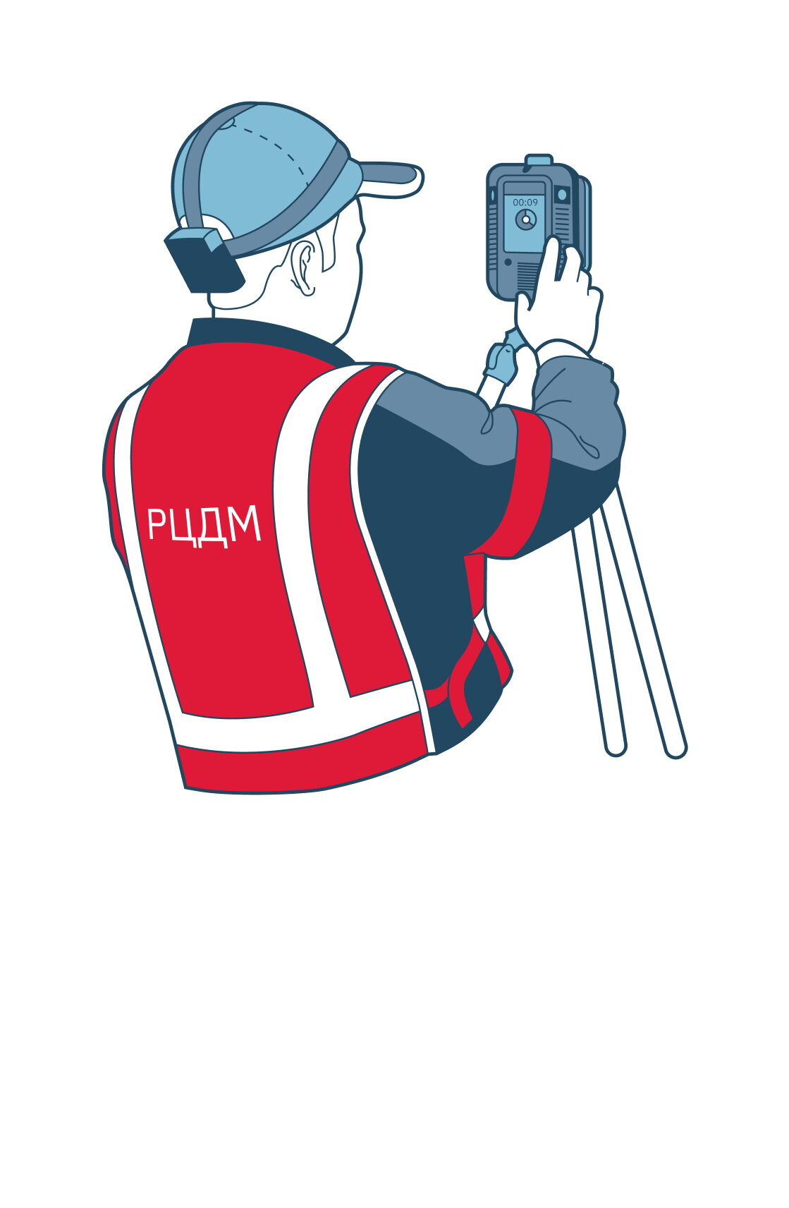
Применение современного оборудования для испытания искусственных сооружений
Описание принципа работы
Испытательное оборудование используется для оперативного определения условий пропуска подвижного состава через искусственные сооружения. В основе работы оборудования лежат многофункциональные измерительные блоки с использованием первичных цифровых и аналоговых датчиков различных типов и номиналов, интеллектуальная система коррекции параметров съёма первичной информации, многорежимная система запуска, динамическое подключение программ обработки данных измерения с экспресс-анализом результатов, автономная работа в режиме сбора данных и передачи данных измерения по каналам связи GSM, GPRS, EDGE, 3G, HSDPA и HSUPA.
Эффекты от внедрения
Оперативное испытание элементов мостовых переходов за счёт применения магнитных датчиков.
Мобильность при транспортировке оборудования.
Увеличенный объём получаемых материалов о состояния элементов сооружения за счёт скорости проведения испытаний.
Ключевые моменты
Проект обеспечивает выполнение требований нормативного документа федерального уровня СП 79.13330.2014 «Мосты и трубы. Правила обследования и испытаний» в части проведения испытаний. Комплекс используется для определения напряжённо-деформированного состояния мостовых конструкций. Данные с комплекса применяются для определения грузоподъёмности мостов. Также данный комплекс применяется для приёмки мостов в постоянную эксплуатацию.
Конструкция комплекса представляет собой устройство распределённо-модульного типа, содержащее систему блоков сбора информации, сопряжённых с многофункциональными первичными датчиками и системой комбинированной (беспроводной или проводной) связи между блоками и полевым контроллером.
Программный продукт комплекса включает:
- программу сбора и первичной обработки информации
- программу коррекции параметров датчиков
- программу расчёта и визуализации и передачи данных измерения.
Измерительный блок имеет многорежимную систему запуска измерений по выбранному входному сигналу в автоматическом (программируемые критерии автозапуска), программном (по таймеру) и ручном режимах; связь с датчиками по цифровым каналам; связь с полевым контроллером по беспроводному интерфейсу связи типа Bluetooth.
Система поддерживает одновременную работу с любым набором первичных преобразователей (датчиков).
Элементы комплекса имеют среднюю наработку на отказ не менее 5 000 ч при условии выполнения установленных периодических видов технического обслуживания.
Техническая информация
Магнитные тензодатчики
5 шт.
Датчик инклинометр-акселерометр (ВД)
3 шт.
Температурный датчик
1 шт.
Блоки сбора и обработки информации
1 шт.
Резервный источник питания
1 шт.
Степень пылевлагозащиты
IP66, IP68
Диапазон рабочих температур
от −30 до +50 °С
Длительность работы в автономном режиме
до 20 ч
Длительность работы в режиме экспресс-управления
до 8 ч
Вес (со стандартным комплектом аппаратуры и сумкой)
до 3 кг
Система информирования машиниста СИМ
Описание принципа работы
На основе модельного ряда систем автоведения разрабатывается следующее поколение интеллектуальных систем, повышающих эффективность работы железнодорожного транспорта, обеспечивающих безопасность движения, экологичность и отвечающих всем последним тенденциям развития электровозостроения в России и Европе. Аналогичных зарубежных и отечественных систем автоведения грузовых электровозов с функциями информирования машиниста, автоматизированным получением и выполнением энергооптимального расписания на данный момент не существует.
Эффекты от внедрения
Уменьшение вероятности обрывов состава и выдавливания вагонов при ручном управлении за счёт наглядного представления состава на профиле, рекомендуемой скорости и обрывоопасных мест.
Указания машинисту на оборудованных участках занятости впереди лежащих пяти блок-участков.
Наглядное отображения в графической форме всех ограничений скорости, включая временные.
Снижение утомляемости и повышение уровня бодрствования машиниста за счёт постоянного контроля его состояния.
Активация внимания машиниста на изменения сигналов светофоров, требующих повышенной бдительности и немедленных действий при помощи речевых сообщений и информации на дисплее.
Применение системы, обеспечивающей информационную поддержку деятельности локомотивных бригад в сложных поездных ситуациях, особенно в ночные и утренние часы, в плохих погодных условиях (снег, дождь, туман) на сложном профиле.
Ключевые моменты
Экономическая эффективность от модернизации универсальной системы автоведения грузового электровоза с добавлением функции системы информирования машиниста достигается за счёт сокращения эксплуатационных расходов и повышения уровня безопасности движения. Обеспечивается экономия электроэнергии на тягу каждым оборудованным системой локомотивом.
Экономия электроэнергии достигается за счёт минимизации общего потребления электроэнергии множеством грузовых поездов на всём полигоне, для которого строится, передаётся на борт и реализуется энергооптимальный суточный график движения грузовых поездов. На борт локомотива принимается, а в режиме автоведения точно исполняется энергооптимальное расписание движения конкретного поезда. Программное обеспечение системы осуществляет расчёт траектории движения, исполнение которой минимизирует потребляемую энергию при точном выполнении принятого энергооптимального расписания в условиях конкретной поездной обстановки. Для расчётов используется математический метод минимизации механической работы по перемещению поезда заданной массы по заданному профилю с учётом ограничений скорости, а также информация электронной базы данных: расписание, план и профиль пути, постоянные и временные ограничения скорости и т. д.
Воздухосборник с управляющей аппаратурой ВУПЗ-12Э
Описание принципа работы
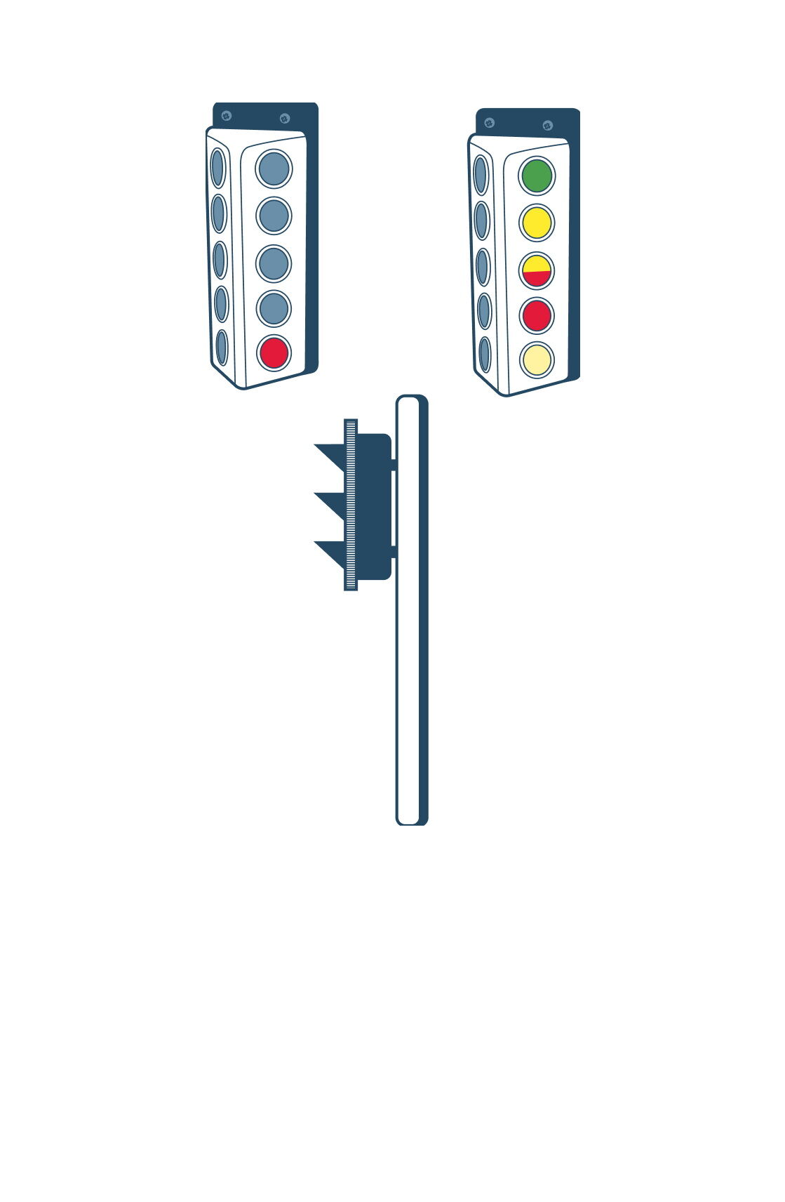
Предназначен для дистанционного электропневматического управления потоком сжатого воздуха между компрессорной установкой, вагонным замедлителем и атмосферой по командам с горочного поста управления, а также для обмена информацией с системой управления.
Эффекты от внедрения
Увеличенное число ступеней торможения до 8 (16 опционально).
Контроль параметров ВУПЗ-12Э на панели управления и через систему управления.
Раздельное управление блоками клапанов.
Улучшенная система грозозащиты и низкое энергопотребление.
Выполнение последних требований по безопасности роспуска (функционирование при отсутствии питания 220 В, наличие входных сигналов более чем на двух линиях при отказе одного датчика давления, блокировка самоподъёма замедлителя, тест линий системы управления).
Ключевые моменты
В зависимости от номинального напряжения электроуправления и внутреннего напряжения питания воздухосборники с управляющей аппаратурой ВУПЗ-12Э изготавливаются в двух исполнениях (указываются при заказе): 24 В постоянного тока (ВУПЗ-12Э 24В) или 48 В постоянного тока (ВУПЗ-12Э 48В).
Воздухосборник с управляющей аппаратурой ВУПЗ-12Э может применяться как взамен воздухосборников с управляющей аппаратурой ВУПЗ-72, ВУПЗ-05М, ВУПЗ-05Э на действующих сортировочных горках, так и при проектировании новых сортировочных горок.
Техническая информация
Ёмкость воздухосборника
0,3 м³
Рабочее давление сжатого воздуха на входе изделия
0,4–0,8 МПа
Напряжение источника переменного тока частотой 50 Гц, используемое для питания и обогрева
Uп, В 220 + 22
Управляющее напряжение на входах клеммной коробки
Uупр, В 24 ± 9 или 48 ± 18
Время срабатывания при «торможении» по команде Т4
не более 100 мс
Время срабатывания при «торможении» по команде Р
не более 120 мс
Мощность, потребляемая по цепи питания 220 В
не более 100 Вт
Время переключения ВУПЗ-12Э с одной ступени торможения на другую
не более 120 мс
Габаритные размеры (Д × Ш × В)
не более 2 200 × 1 050 × 1 120 мм
Установочные размеры для крепления
930 ± 2 × 470 ±2 мм
Межосевой диаметр окружности под болты
160 мм
Диаметр отверстий под болты
18 мм
Количество отверстий под болты
4 шт.
расстояние между отводами
640 мм
Дальность действия пятипроводной схемы управления в нормальном режиме (без дублирования жил диаметром 0,9 мм)
не менее 1 000 м
Дальность действия схемы подключения источника переменного тока (без дублирования жил диаметром 0,9 мм)
не менее 1 000 м
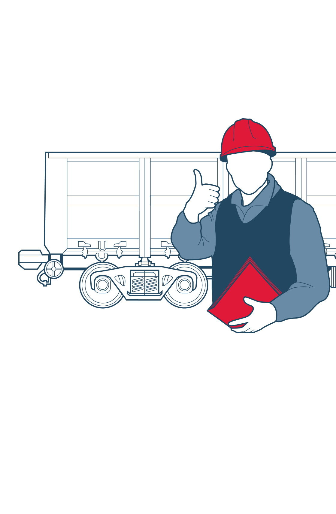
Совмещённое техническое обслуживание и коммерческий осмотр грузовых вагонов (Д)
Описание принципа работы
Утверждена технология совмещённого технического обслуживания и коммерческого осмотра грузовых вагонов № 2500р от 28 сентября 2022 года утв. ЦЗ-1. Данная технология прошла апробацию на железнодорожной станции Челябинск-Главный. Для апробации на Дальневосточной железной дороге предлагается рассмотреть в режиме опытного применения железнодорожную станцию Хабаровск-II, парк «А». На данный момент в парке работает в одну смену бригада из трёх человек: один оператор АСКО ПВ и два человека в парке, которые осматривают передачи с Хабаровска-I (данные поезда не проходят АСКО ПВ) и «выводки» с Чётного сортировочного парка.
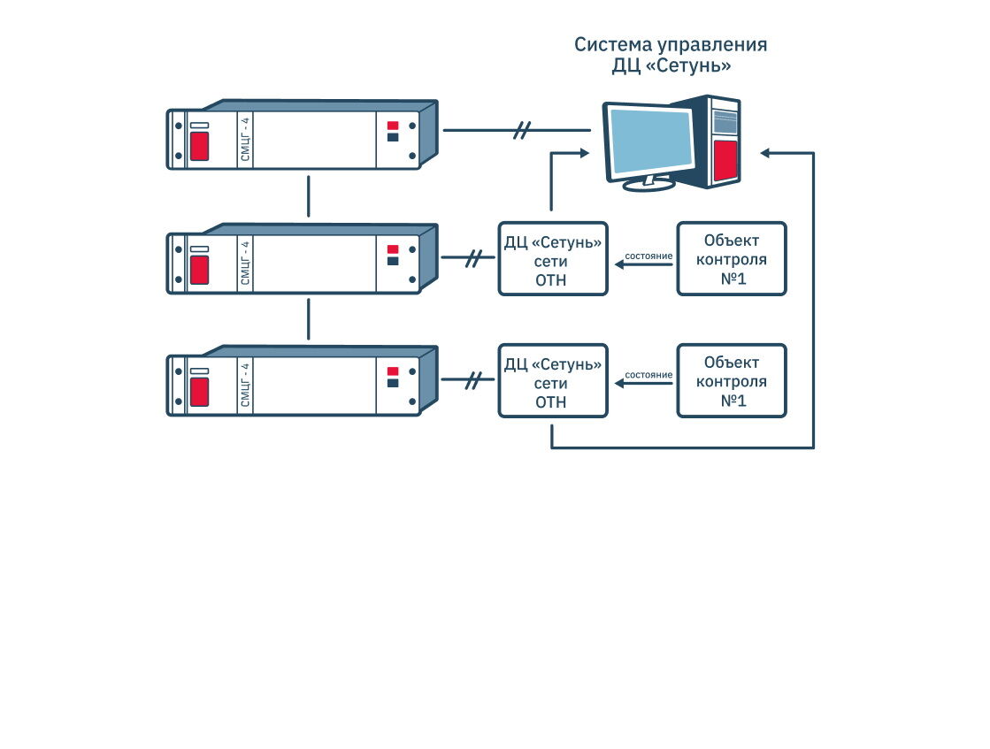
Система электрической централизации ЭЦК-03
Описание принципа работы
В декабре 2022 года в рамках реализации инвестиционного проекта «Мероприятия по увеличению пропускной и провозной способности инфраструктуры для увеличения транзитного контейнеропотока в 4 раза, в т. ч. Транссиб за 7 суток» введены в эксплуатацию путевые посты (ПП 1 234 км, ПП 1 251 км и ПП 1 501 км), оборудованные системой электрической централизации ЭЦК-03 и управлением с электронного пульта управления АРМ ДСП в системе ДЦ «Сетунь» со станции Новый Уоян и разъезда Лодья. Данная система на дороге введена и эксплуатируется впервые.
Ключевые моменты
Отсутствие ДСП на путевом посту, в связи с возможностью удалённого управления с соседней станции.
Электронный пульт управления подключается к устройствам по каналу связи с использованием витой пары и подключением его к гарантийному питанию.
Возможность постоянного архивирования действий.
Возможность логического контроля за неисправностями устройств СЦБ.
Лучшая эргономика восприятия экрана, возможность изменения палитры экрана (дневной/ночной режим).
Мобильность рабочего места ДСП.
Гарантийные участки от станции погрузки до станции выгрузки протяжённостью до 6 000 км
Описание принципа работы
23.06.2022 на заседании секции «Вагонное хозяйство» Научно-технического совета ОАО «РЖД» (протокол от 23.06.2022 № 15) одобрено поэтапное установление гарантийных участков безопасного проследования вагонов в исправном состоянии в составе поезда протяжённостью до 6 000 км от станций погрузки до станций выгрузки груза.
Эффекты от внедрения
Установление гарантийных участков подразумевает:
— уменьшение времени, затрачиваемое на доставку груза;
— сокращение времени простоя вагонов на пунктах технического обслуживания; оптимизацию эксплуатационной работы, а также дальнейшее — совершенствование технического обслуживания грузовых вагонов.
ОАО «РЖД» устанавливает гарантийные участки безопасного проследования грузовых поездов в исправном состоянии на основании данных, предоставленных и согласованных каждой железной дорогой.
Поэтапное установление гарантийных участков предусматривает беспрерывный анализ формирования и отправления грузовых поездов от станции погрузки до станции выгрузки груза для выявления, рассмотрения и предложения необходимых гарантийных участков.
Ключевые моменты
При установлении новых гарантийных участков рассматривается работа пунктов технического обслуживания вагонов, проводится согласование и внесение изменений в технологические процессы в работе станций и ПТО в части установленных гарантийных участков безопасного проследования вагонов в исправном состоянии в составе поезда и утверждённых местных норм времени на ПТО. Также рассматривается создание на ПТО необходимого запаса деталей и узлов для технического обслуживания и ремонта вагонов.
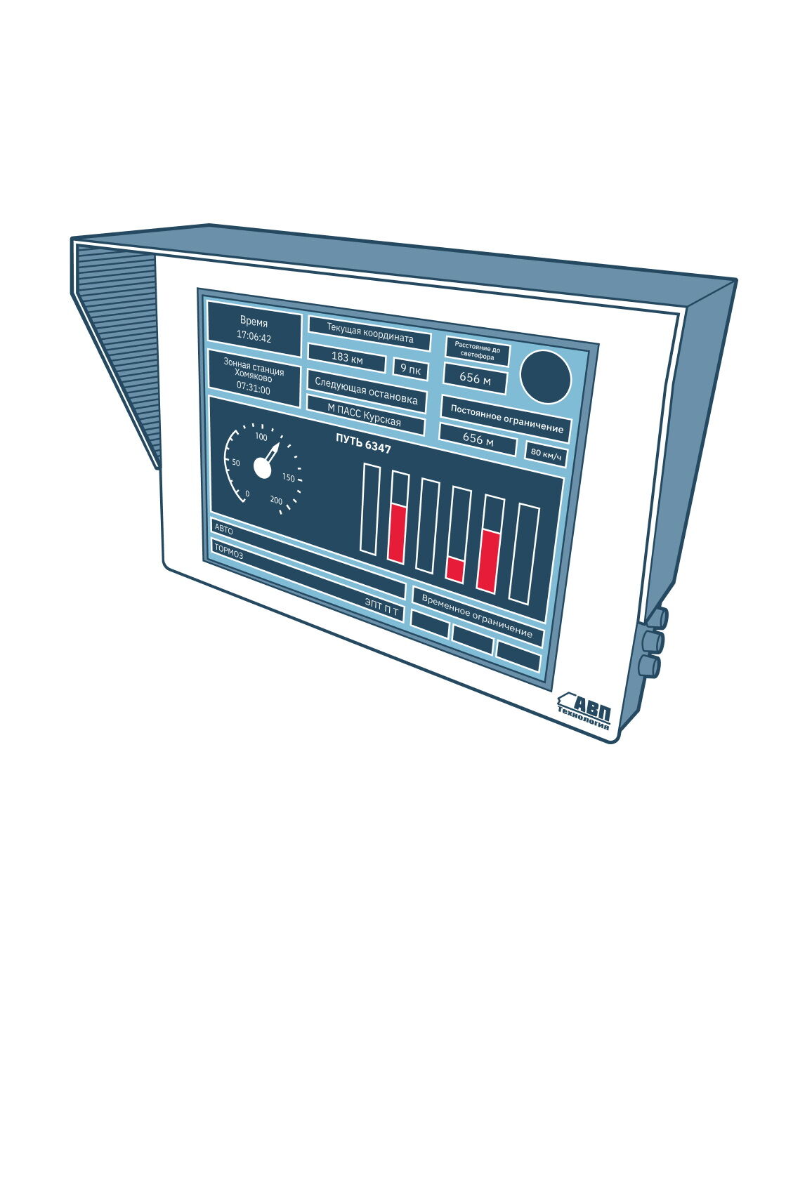
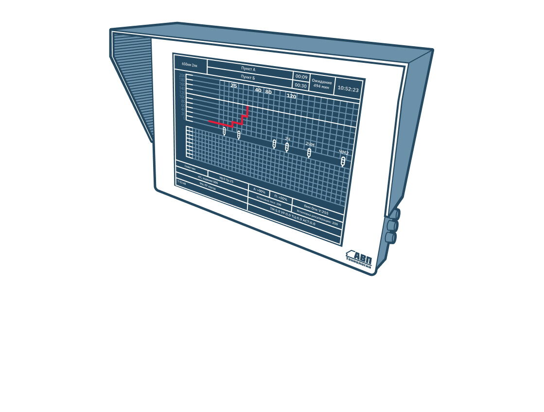
Универсальная система автоведения магистральных тепловозов УСАВП-Т
Описание принципа работы
Система УСАВП-Т предназначена для автоматизированного управления режимом тяги и всеми видами торможения магистральных тепловозов. Она обеспечивает автоматизированное ведение магистрального тепловоза на основе выбора режима ведения поезда, рационального по расходу топлива, с точным соблюдением времени хода. Интегрированная в УСАВП-Т подсистема регистрации параметров РПДА-ТМ обеспечивает сбор, обработку, регистрацию на съёмный носитель данных о расходе топлива, работе тепловоза, местоположении, а также их передачу РОРС GSM.
Эффекты от внедрения
Сокращение расхода дизельного топлива тепловозами на 8 %.
Экономия годовых эксплуатационных расходов за счёт повышения надёжности работы силового оборудования путём допускового контроля основных параметров ДГУ.
Снижение эксплуатационных расходов на ремонт тепловозов за счёт своевременного проведения технического обслуживания по результатам анализа параметров, зарегистрированных системой, расшифрованных и полученных в АРМ.
Экономия годовых эксплуатационных расходов за счёт снижения резерва локомотивных бригад, обусловленной снижением уровня психофизиологической нагрузки и затрат по листам нетрудоспособности.
Повышение безопасности движения поездов.
Создание условий для организации обслуживания локомотива в одно лицо.
Ключевые моменты
Система информирует машиниста о следующих параметрах:
— значении расчётной скорости с точностью ±1 км/ч;
— значении фактической скорости поезда с точностью ±1 км/ч;
— времени прибытия на ближайшую зонную станцию с точностью ±10 с;
— оставшемся расстоянии до контрольной станции с точностью 100 м (1 пикет);
— значении скорости и координате начала ближайшего временного ограничения скорости с точностью индикации 100 м;
— позиции контроллера машиниста в режиме тяги или ЭДТ;
— режиме торможения (перекрыша, торможение, отпуск) с указанием вида основного тормоза (ЭПТ, ПТ, ЭДТ).
Дополнительно машинист получает следующую информацию:
— астрономическое время с дискретностью 1 с;
— координату местонахождения поезда (км, пикет);
— максимально разрешённую позицию тяги;
— номер и название перегона, на котором находится поезд;
— диаметр обода колеса (бандажа) колёсной пары, на которой установлен датчик ДПС;
— отклонение от расписания;
— звуковое предупреждение о приближении к местам, требующим повышенного внимания.
Техническая информация
Напряжение питания (бортовая сеть)
110 В
Диапазон отклонения от номинального значения
35–140 В
Дисплей цветной графический
TFT
Сетевое программное обеспечение
CAN open
Потребляемая мощность
не более 150 Вт
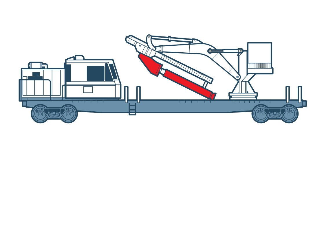
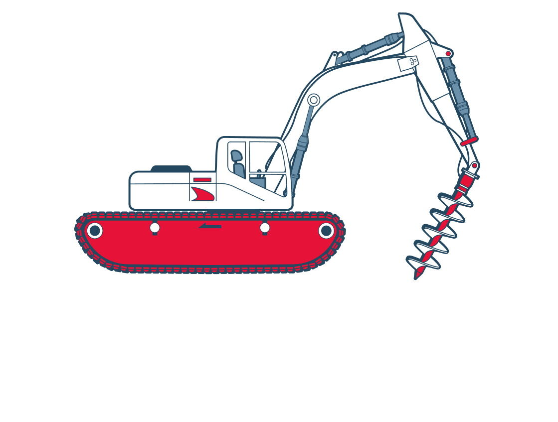
Универсальный комплекс для бурения скважин в скальных породах
Описание принципа работы
Комплекс, предназначенный для бурения скважин в скальных грунтах под опоры контактной сети электрифицированных железных дорог, установки фундаментов и опор контактной сети и ЛЭП, завинчивания фундаментов и выполнения погрузочно-разгрузочных работ.
Ключевые моменты
Комплекс должен соответствовать настоящим техническим требованиям, а также требованиям ГОСТ 32216.
Разработка скважин в скальных породах пневмоударным рабочим органом под установку свайных фундаментов ФБС, АБС, ФТП, ФСТП, ФТ, ФСТ, АСТ, АТ.
Использование сменного шнекового бурового оборудования (L — не менее 4,5 м, Ø — не менее 0,36 м) в грунтах VII категории.
Работа крано-манипуляторной установкой погружения фундаментов, установка опор контактной сети, погрузочно-разгрузочные работы.
Вписывание машины в габарит подвижного состава «Т» (по ГОСТ 9238) при движении в составе поезда или самоходом с любым сменным оборудованием.
Задний габарит рабочего оборудования, развёрнутого поперёк пути — не более 2 000 мм.
При работе комплекса в технологическом цикле и при его транспортировке с любым сменным оборудованием нагрузки на ходовые части базовой платформы соответствуют нормативным требованиям.
Перевод рабочего оборудования из транспортного положения в рабочее и обратно под контактной сетью без её демонтажа или отвода при габарите подвески 5 750 мм от уровня головки рельса.
Поперечную устойчивость комплекса с любым сменным оборудованием при переводе оборудования из транспортного положения в рабочее и обратно, в том числе при работе комплекса на кривых участках железнодорожного пути радиусом не менее 150 м с превышением наружного рельса до 150 мм, при работе крана-манипулятора, а также при транспортировании в составе грузового или хозяйственного поезда со скоростью до 80 км/ч.
Время приведения комплекса в транспортное положение в штатном режиме — не более 15 мин., а в аварийном — не более 20 мин. (действия экипажа в аварийных ситуациях указаны в руководстве по эксплуатации).
Техническая информация
Максимальная масса комплекса (две платформы)
80 (140) т
Фитинговая железнодорожная платформа (в зависимости от комплектации)
2 ед.
Погружной пневмоударник
62,5
Максимальный расход воздуха при давлении 16 бар
62,5 м³/мин
Диаметр бурения
400–550 мм
Максимальный наружный диаметр корпуса
330 мм
Максимальная длина пневмоударника без коронки
2 389 мм
Максимальный вес без коронки
1 030 кг
Транспортный габарит
«Т» по ГОСТ 9238
Элемент оборудования
Зажим для раскручивания штанг
Максимальный диаметр штанг
360 мм
Минимальный момент раскручивания при давлении 170 кг/см²
5 800 кГм
Максимальная скорость передвижения в составе грузового поезда
80 км/ч
Метеорологические условия
от −40 до +40 ºС
Элемент оборудования
Рабочий орган (гидравлический манипулятор)
Максимальный угол поворота стрелы манипулятора в горизонтальной плоскости
90°
Минимальный грузовой момент на стреле манипулятора
28 т/м
Управление
из кабины управления
Элемент оборудования
Винтовой компрессор КВ 20/25
Минимальное количество (может быть больше при размещении комплекса на двух или более ж/д платформах)
2 шт.
Минимальная мощность одной дизельной установки
243 кВт
Минимальное номинальное давление одного компрессора
1,6 МПа
Минимальная производительность одного компрессора
25 м³/мин
Максимальная масса одного компрессора
4,5 т
Элемент оборудования
Силовая установка: дизель-гидроэлектрическая
Минимальная номинальная мощность генератора
100 кВт
Минимальная номинальная мощность гидростанции
25 кВт
Минимальное давление в гидросистеме
20 мПа (200 кг/см²)
Элемент оборудования
Кран-манипулятор гидравлический
Минимальный грузовой момент
290 кН·м (28,8 тм)
Минимальный угол поворота
400°
Управление
со стационарного пульта и с дистанционного выносного пульта
Элемент оборудования
Навесная люлька
Минимальная грузоподъёмность
250 кг
Минимальная грузоподъёмность на максимальном вылете
400 кг
Элемент оборудования
Навесное быстросъёмное оборудование для бурения лидирующих скважин
Минимальный диаметр
0,36 м
Элемент оборудования
Вращатель дополнительного сменного оборудования
Максимальная частота вращения при бурении
125 1/мин
Максимальная частота вращения при завинчивании
10 1/мин
Максимальный крутящий момент на выходном валу вращателя при бурении
20 кН·м
Максимальный крутящий момент на выходном валу вращателя при завинчивании
100 кН·м
Элемент оборудования
Постоянный магнитный подъёмник ПМЛ-3
Максимальная грузоподъёмность
300 кг
Максимальное напряжение
220 В
Максимальная мощность
6 кВт
Обслуживающий персонал
2 человека
Вагон испытания контактной сети (НТЭ)
Описание принципа работы
ВИКС предназначен для оценки состояния устройств контактной сети электрифицированных железных дорог. Контролируемые параметры контактной сети регистрируются в реальном времени с высокой точностью.
Эффекты от внедрения
Задачи, которые выполняет ВИКС:
— бесконтактное измерение высоты КП над уровнем верха головок рельсов в диапазоне 5 500–6 900 мм с погрешностью не более ±10 мм;
— бесконтактное измерение положения КП (зигзаг и вынос) в плане при количестве проводов от одного до четырёх в диапазоне ±700 мм с погрешностью не более ±10 мм;
— контроль понижения КП на воздушных стрелках, положение по высоте фиксаторов и отходящих анкеровочных ветвей относительно основного КП;
— измерение нажатия токоприёмника на КП в диапазоне 0–400 Н с погрешностью не более ±10 Н;
— регистрация ударов по токоприёмнику в диапазоне ускорений 0–50 g;
— регистрация отрывов токоприёмника от КП по мгновенному падению измеряемого напряжения КС в течение 200 мс и более, в соответствии с распоряжением №348р от 21.02.2018 «Методика определения балльной оценки состояния контактной сети в Трансэнерго»;
— автоматическая отметка опор;
— измерение наклона кузова вагона относительно букс колёсных пар;
— измерение скорости движения ВИКС в диапазоне 1–200 км/ч с погрешностью не более ±2 км/ч;
— измерение пройденного ВИКС расстояния;
— измерение и контроль параметров при движении ВИКС со скоростями в диапазоне 0–160 км/ч;
— выполнение измерений синхронно с другими измерительными системами и комплексами ВИКС с привязкой к глобальной навигационной спутниковой системе ГЛОНАСС/GPS и железнодорожной системе координат (при наличии базы данных объектов инфраструктуры);
— измерения напряжения в КС в диапазоне 2,7–4,0 кВ постоянного тока с погрешностью не более 10 % и в диапазоне 21–29 кВ переменного тока с частотой 50 Гц с погрешностью не более 10 %;
— измерение температуры наружного воздуха в диапазоне от −50 до + 40 °С с погрешностью не более ±2 °С.
Беспилотный летательный аппарат для обследования водоотводных устройств земляного полотна
Описание принципа работы
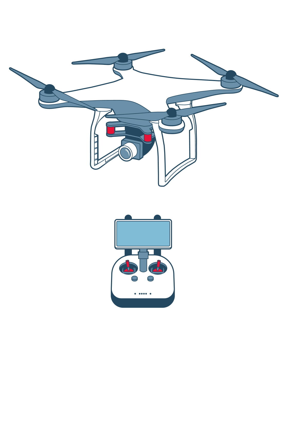
Предназначен для визуального обследования и контроля состояния водоотводных сооружений, скально-обвальных и лавиноопасных участков инфраструктуры железнодорожного транспорта.
Эффекты от внедрения
Снижение натурных осмотров объектов инфраструктуры за счёт применения безлюдных технологий.
Ключевые моменты
Оценка состояния искусственных инженерных сооружений, мониторинг потенциально опасных экзогенных геологических и гидрологических процессов (оползней и подмывов берегов рек), а также потенциально опасных геологических проявлений в районе распространения многолетнемёрзлых пород. Построение ортофотопланов и 3D-моделей. Вывод человеческого ресурса из опасных зон обследования и диагностики инфраструктуры.
БПЛА должен обеспечивать:
- фото- и видеосъёмку сооружений и объектов инфраструктуры железнодорожного транспорта
- быстрый осмотр и оценку труднодоступных зон
- мониторинг скально-обвальных и лавиноопасных участков
- доступ к местам наблюдения или мониторинга, представляющим опасность для людей
- возможность получения снимков/видеозаписей неисправностей и дефектов с качеством разрешения не ниже 4К на допустимой высоте
Обеспечение безопасности полёта БПЛА осуществляется при помощи сенсорной системы, предотвращающей столкновение с препятствиями.
Электромагнитная совместимость с другими техническими средствами ОАО «РЖД» позволяет исключить влияние на них электромагнитных помех от БПЛА.
Наземная станция управления (НСУ) должна обеспечивать полностью автоматическое управление БПЛА на всех этапах полёта.
Техническая информация
Максимальная взлётная масса
1,5 кг
Максимальное разрешение камеры в видимом диапазоне
не ниже 4K (3 840 × 2 160 пикс.)
Стабилизация камеры
гиростабилизация по 3 осям
Продолжительность полёта на одном комплекте батарей в штиль
от 25 мин.
Рабочая температура
от 0 до 40 ºC
Количество совместимых АКБ на один БПЛА
от 5 шт.
Диагональ штатного экрана
от 13 см
Максимальная высота от точки взлёта
500 м, над уровнем моря — 6 000 м
Депо путевых машин
Описание принципа работы
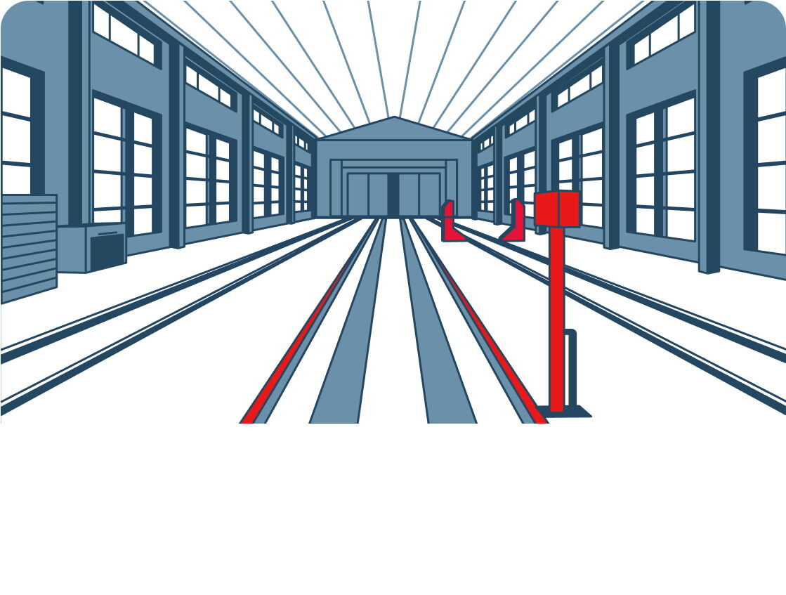
Строительство «Депо путевых машин» в путевой машинной станции № 303, Кичера. Дефицит провозных мощностей Российских железных дорог в Восточном направлении остаётся одной из главных проблем. Компания ОАО «РЖД» разработала план ускоренной модернизации Байкало-Амурской магистрали (БАМ) для увеличения провозных способностей в направлении морских портов и пограничных переходов Дальнего Востока. Для реализации новых проектов необходимо развитие инфраструктуры, доведение технической оснащённости линейных предприятий железнодорожного транспорта до высокотехнологического уровня. С этой целью 2 августа 2021 года на производственной базе Путевой машинной станции № 303 на станции Кичера, запущен в эксплуатацию бытовой эксплуатационный корпус для проведения текущих ремонтов путевой машинной техники. До этого дня у предприятия отсутствовали производственные мощности для проведения текущего ремонта приписного парка техники, а техническое обслуживание в суровых климатических условиях проводилось под открытым небом.
Эффекты от внедрения
Появилась возможность производить более качественный ремонт машин и механизмов круглогодично, невзирая на погодные условия.
Удалось создать достойные санитарно-бытовые условия для работников, повысить производственные возможности предприятия и его привлекательность для новых рабочих кадров.
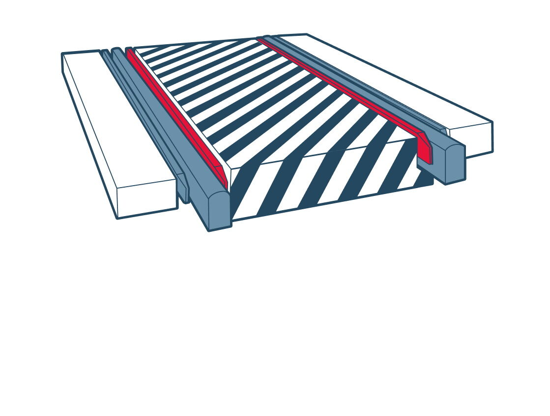
Синтетический трос
Описание принципа работы
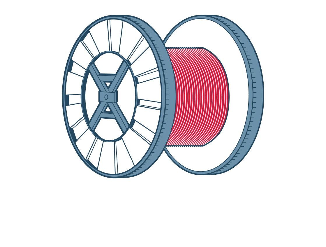
В 2023 году в технологический процесс перетяжки пакетов рельсошпальной решётки внедрён синтетический трос из сверхвысокомолекулярного полиэтилена, более гибкий и имеющий в пять раз меньшую массу по сравнению со стальным тросом. При использовании синтетического троса уменьшается трудоёмкость процесса его растягивания, а также сокращается время на перетяжку пакетов рельсошпальной решётки.
Эффекты от внедрения
Благодаря внедрению синтетического троса в технологию перетяжки пакетов рельсошпальной решётки в путевой машинной станции № 66 ст. Вихоревка реализованы следующие задачи:
— повышение эффективности перетяжки пакетов рельсошпальной решётки на 7 %;
— увеличение срока службы тросов в данной технологии производства работ в 1,8 раза;
— улучшение условий труда работников, производящих перетяжку пакетов рельсошпальной решётки.
Ключевые моменты
Доходы предприятия формируются за счёт повышения эффективности перетяжки пакетов рельсошпальной решётки, увеличения срока службы тросов в данной технологии работ, а также экономии фонда оплаты труда работников, задействованных на перетяжке пакетов рельсошпальной решётки и участвующих в замене троса. Экономический эффект составил 1 437 800 рублей.
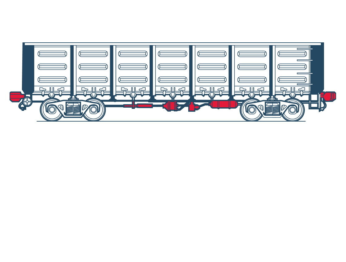
ППСС
Описание принципа работы
Предназначен для автоматизации процессов технического и коммерческого осмотра, исключения дублирования технологических операций в парках приёма и отправления, централизации принятия решений, автоматизации документооборота и повышения уровня достоверности результатов контроля при обработке состава.
ППСС реализован на основе технологий:
- машинного зрения (распознавание знаков опасности, трафаретных надписей, инвентарных номеров, определение завышения или занижения фрикционных клиньев, износ тормозной колодки и др.)
- лазерного 3D-сканирования (выявление отрицательной динамики, нарушений габаритов, повреждений кузовов вагонов, открытых дверей, люков, бортов платформ и др.)
- тензометрии (измерение массы, определение неравномерной загрузки или смещения центра тяжести грузов, обнаружение дефектов поверхностей катания колёс)
- дистанционного считывания информации с бортовых устройств контроля состояния подвижного состава и груза (RFID-пломбы, RFID-метки с данными деталей вагонов, датчики контроля доступа, датчики температуры, датчики дыма, электронные компоненты ЗПУ и др.).
Эффекты от внедрения
Экономия при сокращении времени приёма поезда на станцию.
Экономия фонда оплаты труда за счёт оптимизации штата осмотрщиков-ремонтников вагонов.
Экономия за счёт снижения количества отцепок вагонов в пределах гарантийных участков.
Ключевые моменты
Внедрение ППСС позволяет:
- сократить задержки, приводящие к увеличению времени ожидания обработки состава в парке прибытия в части закрепления;
- сократить задержки поездов у входных светофоров станции, исключить влияние человеческого фактора (ошибочное списывание номеров вагонов, пропуск вагонов);
- исключить затруднения списывания при параллельном заходе поездов на станцию;
- оптимизировать штат осмотрщиков-ремонтников вагонов (ОРВ) эксплуатационного вагонного депо в парке приёма за счёт повышения степени автоматизации, достоверности и адресности результатов диагностики технических неисправностей.
Техническая новизна ППСС подтверждается полученными патентами и свидетельствами о регистрации ПО.
Техническая информация
Режим работы
круглосуточный
Допустимая скорость движения состава в контролируемой зоне
90 км/ч
Максимальное ускорение/замедление подвижного состава в контролируемой зоне
2: ± 0,05 м/с
Максимальная транзитная скорость
250 км/ч
Режим движения состава
непрерывный
Интерфейс передачи информации
Ethernet
Протокол передачи информации
TCP/IP
Напряжение питания постового оборудования, при частоте 50 Гц
переменное однофазное или трёхфазное с фазным напряжением 220 В ± 10 %
Напряжение питания напольного оборудования при частоте 50 Гц
переменное однофазное или трёхфазное с фазным напряжением 220 В ± 10 %
Мощность, потребляемая постовым оборудованием во время проследования поездом точки контроля
до 12 500 Вт
Мощность, потребляемая напольным оборудованием во время проследования поездом точки контроля
до 14 000 Вт
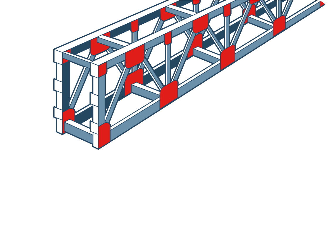
Противопучинные мероприятия (ДКС)
Описание принципа работы
ЦУП ЖАТ (ВЛ) Объект «Электрификация линии Волочаевка-II — Комсомольск-Сортировочный»
Кремнийорганические эмали представляют собой суспензию пигментов и наполнителей в растворах кремнийорганических смол. Противопучинная полимерная термоусаживаемая оболочка остаётся пластичной даже при сильном минусе (до −63 ºС) и не смерзается с грунтом, то есть свая остаётся в исходном положении. Адгезивный слой обеспечивает прочное сцепление оболочки со сваей и не даёт ей сдвигаться по свае (сила касательного сцепления составляет не менее 30 кг/см², что превышает силу морозного пучения в десятки раз).
Эффекты от внедрения
При проектировании оснований и фундаментов на пучинистых грунтах предусматривают специальные противопучинные мероприятия, призванные снизить силы морозного пучения.
Ключевые моменты
Возведение сооружений на пучинистых грунтах и грунтах в зонах сезонного оттаивания зачастую имеет свои объективные сложности. Мерзлотно-грунтовые условия на глубинах промерзания вследствие морозного пучения являются неблагоприятными для несущей способности фундаментов.
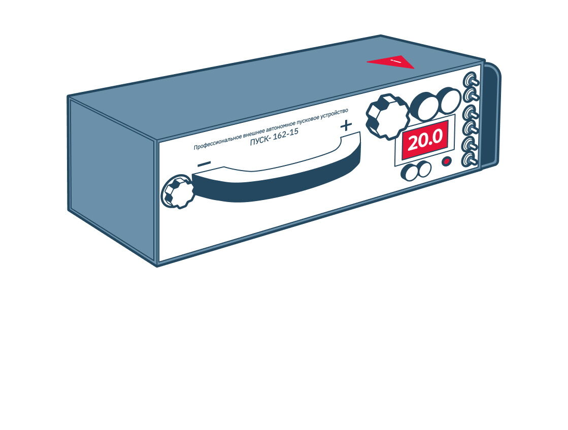
Система гарантированного запуска двигателя (ДРП)
Описание принципа работы
ССГЗД подключается последовательно к АКБ и непосредственно к клеммам стартера. При этом АКБ не участвует в процессе пуска, а используется лишь для зарядки ССГЗД. Модульный принцип позволяет построить оптимальную суперконденсаторную систему гарантированного запуска двигателя.
Эффекты от внедрения
Система гарантированного запуска двигателя ССГЗД предназначена для использования совместно с АКБ со сниженной относительно штатных ёмкостью.
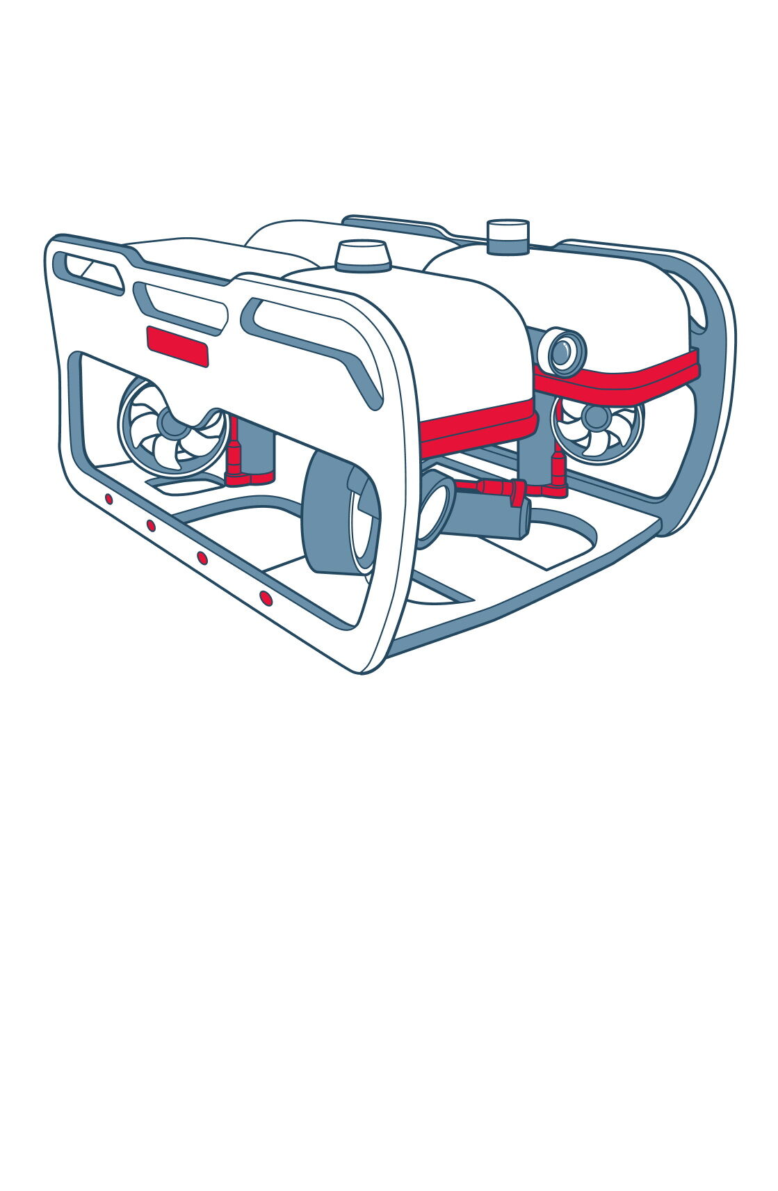
Обследование подводных частей опор мостовых переходов телеуправляемым подводным аппаратом
Описание принципа работы
Телеуправляемый подводный аппарат используется для автономного подводного обследования и мониторинга подводных частей опор мостовых переходов, русел водотоков и сопровождения водолазных работ.
Эффекты от внедрения
Снижение количества водолазных погружений сетевой водолазной обследовательской станцией ОАО «РЖД».
Оперативность проведения водолазных обследований.
Отсутствие необходимости специализированного обучения и приобретения дорогостоящих СИЗ.
Точное определение местоположения неисправности и её параметров за счёт навигационных приборов, применяемых в подводном телеуправляемом аппарате.
Ключевые моменты
Технология обеспечивает выполнение требований нормативного документа федерального уровня СП 79.13330.2014 «Мосты и трубы. Правила обследования и испытаний» в части проведения обследований.
Преимущества данной технологии:
- Автономность. Выполнение работ по обследованию с дистанционным управлением оператором и энергопитанием от переносного источника с пультом дистанционного управления с дальностью хода до 250 м и глубиной до 150 м.
- Мобильность. Транспортировка без использования специальных транспортных и грузоподъёмных средств, простота приведения в состояние готовности. Обеспечение спуска и подъёма вручную без применения специального спускового устройства.
- Манёвренность. Оснащение четырьмя горизонтальными и двумя вертикальными движителями с обеспечением высокой точности и скорости передвижения с изменениями фиксации положений и плавучестью, близкой к нулевой.
- Информативность. Оснащение аппарата двумя фотовидеокамерами высокого разрешения с поворотом видеокамер до 500 и системой качественного подводного освещения с изменением наклона и поворотом светоприводов.
- Управляемость. Управление работами с пульта ручного управления с изменением скорости, глубины и курса, управление камерами и освещением.
Техника с повышенной проходимостью
Описание принципа работы
Работы по строительству контактной сети выполняются в условиях суровой затяжной зимы и дождливого лета. Значительный участок главного пути от станции Волочаевка-II до станции Комсомольск-на-Амуре проходит по болотистой местности при отсутствии дорог для подъезда автотранспорта. В данных условиях для выполнения работ по установке опор и фундаментов контактной сети «с поля» используется техника с повышенной проходимостью: болотоходы и экскаваторы-амфибии, без применения которых темпы строительства были бы значительно ниже.
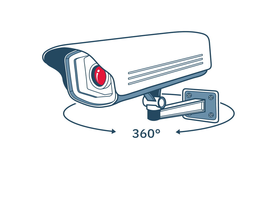
Установка систем видеонаблюдения
Описание принципа работы
Установка системы видеонаблюдения на площадках строительства предоставляет возможность оперативно отслеживать ход стройки. Видеонаблюдение позволяет бригадиру следить за ходом проведения работ, а инженеру по технике безопасности — контролировать выполнение правил.
Эффекты от внедрения
Видеонаблюдение за строительными объектами и за прилегающей к ним территорией в режиме реального времени.
Возможность контроля хода работ без необходимости присутствовать на строительной площадке лично.
Подключение к системе видеонаблюдения по интернету из любой точки земного шара.
Создание непрерывного архива видеозаписей с камер наблюдения.
Возможность демонстрации хода работ и готовности объекта для инвесторов без их присутствия на объекте.
Видеоконтроль состояния верхнего строения пути
Описание принципа работы
Система видеонаблюдения объектов инфраструктуры предназначена для непрерывного визуально контроля и обнаружения дефектов на поверхности катания рельсов и отслеживания состояния элементов рельсовых скреплений. Современные мобильные средства диагностики и диагностические комплексы оборудованы высокоточной системой видеофиксации верхнего строения пути с автоматической расшифровкой отступлений от норм содержания, таких как величина стыковых зазоров, отсутствующие стыковые болты, излом накладок, отсутствующие или дефектные скрепления, дефектные шпалы, дефекты рельсов на поверхности катания, подвижки рельсовых плетей, наличие щебня в шпальных ящиках и т. д. Система состоит из четырёх видеокамер (две камеры на каждый рельс), расположенных под вагоном и направленных на рельс под углом 90°. Это позволяет выявлять неисправности, влияющие на безопасность движения поездов, в режиме реального времени.
Эффекты от внедрения
Система видеоконтроля обеспечивает надёжное автоматическое определение дефектов в элементах верхнего строения пути и на поверхности катания рельсов.
Ключевые моменты
Определение и оценка смещения рельсовых плетей относительно «маячных» шпал.
Определение параметров и размеров дефектов шпал и переводных брусьев.
Определение кустовой негодности шпал.
Фиксация шпал с разворотом относительно своей оси.
Определение наличия и протяжённости разжижения балластного слоя.
Определение наличия отсутствующих и неработающих противоугонов.
Определение наличия и оценка состояния рельсовых скреплений.
Определение и оценка соблюдения эпюры шпал.
Определение и оценка перпендикулярности шпалы относительно оси пути.
Определение и оценка состояния шпал и переводных брусьев.
Регистрация видеоинформации высокого разрешения о состоянии верхнего строения пути (от торца до торца шпалы).
Определение двух подряд и более нулевых зазоров.
Определение наличия и состояния (надрыв, трещина, излом) накладок.
Определение наличия и состояния стыковых болтов (ослаблен, раскручен, не типовой).
Определение наличия видимых повреждений изоляции в изолирующих стыках.
Видеоконтроль элементов верхнего строения пути и обзорное видеонаблюдение должны охватывать также устройства железнодорожной автоматики и элементы заземления контактной сети в пределах рельсошпальной решётки и в полосе отвода, в частности следующие элементы: изолирующие стыки, маячные метки, стыковые зазоры, дроссельные трансформаторы, путевые коробки, перемычки, шлейфы САУТ, УКСПС, релейные, аккумуляторные шкафы, светофоры и др.
Камеры обзорного видеонаблюдения должны формировать цветное изображение. Камеры должны быть расположены в защищенном месте и обеспечивать фронтальное изображение всей системы.
Для камер обзорного видеонаблюдения должен быть предусмотрен автоматических переход между режимами день/ночь за счёт автоматического отключения инфракрасного заграждающего фильтра в условиях недостаточной освещённости. Данные системы видеонаблюдения должны иметь привязку, соответствующую привязке всех измерительных систем комплекса и записываться совместно со всеми прочими измерительными данными на СХД.
Просмотр данных системы обзорного видеонаблюдения должен иметь возможность пакетного вывода изображений по фильтру типа объекта из базы данных (светофор, стрелочный перевод, переезд, мост и пр.).
Система обзорного видеонаблюдения должна также фиксировать состояние опор контактной сети по ходу и против хода движения ДКИ.
Техническая информация
Количество линейных камер (сканирующих устройств)
от 4 шт.
Разрешение получаемого цветного изображения
1 920 × 1 080 пикс.
Частота формирования кадров
от 1 кадра на 1,8 м пути
Скорость контроля
0–160 км/ч
Погрешность в вычислении размеров поверхностных дефектов рельсов и седловин
±1 мм
Оценка ширины стыкового зазора
0–50 ± 1 мм
Погрешность в оценке перпендикулярности шпалы относительно оси пути
± 0,02°
Оценка смещения рельсовых плетей относительно «маячных»
диапазон измерений 1–500 шпал, погрешность ± 1 мм
Параметры и размеры дефектов шпал, мостовых и переводных брусьев
погрешность ± 1 мм (подтверждается оператором)
Определение наличия и протяжённости разжижения балластного слоя
0,5–100 м ± 0,5 мм
Пролётные строения из атмосферостойкого металлопроката (ДИ)
Описание принципа работы
В рамках инвестиционной программы ОАО «РЖД» на полигоне Дальневосточной железной дороги применяется установка металлических пролётных строений из атмосферостойкого металлопроката марки 14ХГНДЦ. В 2023–2024 годах будут сданы в эксплуатацию три моста через реки Амгунь, Куркальту и Орокот с применением атмосферостойкого металлопроката. Это позволяет исключить в последующем покраску пролётных строений.
Эффекты от внедрения
Установлены и успешно эксплуатируются в трёх различных регионах страны три пролётных строения длиной 55 м, изготовленные Воронежским заводом из стали марки 14ХГНДЦ: на Юго-Восточной ж/д (мост через р. Ворона), на Южно-Уральской ж/д (мост через р. Камышлы-Аят) и на Восточно-Сибирской ж/д (мост через р. Снежная у берега оз. Байкал). Все до сих пор не окрашены. Результаты обследования в 2010 году показали удовлетворительное состояние металлоконструкций.
Регистратор параметров движения и автоведения пригородных электропоездов РПДА-ПТ
Описание принципа работы
Предназначен для измерения и регистрации до 30 основных параметров движения электропоезда в реальном времени в течение всей поездки.
Расшифровка зарегистрированных данных позволяет оперативно оценивать техническое состояние электропоезда, своевременно проводить профилактические и ремонтные работы, сокращать их продолжительность и трудозатраты ремонтного персонала, а также контролировать выполнение расписания движения и правильность управления поездом. Разработаны и внедряются две модификации регистраторов: РПДА — для электропоездов постоянного тока, РПДА-ПТ — для электропоездов переменного тока. Система устанавливается на всех моторных вагонах электропоезда, от которых информация передаётся в блок регистрации, расположенный в головном вагоне. Передача информации осуществляется по каналу связи FSK с использованием штатных межвагонных проводов электропоезда.
Эффекты от внедрения
Сокращение трудозатрат, связанных с ручной расшифровкой скоростемерных лент.
Повышение точности учёта и планирования расхода электроэнергии.
Снижение трудозатрат по учёту и анализу расхода электроэнергии.
Сокращение затрат на проведение диагностики и ремонта электропоездов.
Ключевые моменты
Наиболее близким аналогом РПДА является скоростемерная лента. Функциональные возможности РПДА, отличающие их от упомянутого аналога, позволяют:
1. Ремонтным службам — осуществлять оценку технического состояния электропоезда (синхронность работы главных контроллеров (КСП), наличие индуктивных шунтов, позиции КСП моторных вагонов, величину токов, уставки реле ускорения, время срабатывания высоковольтного выключателя (ВВ), реле боксования (РБ), для проведения его ремонта по техническому состоянию.
2. Службе эксплуатации — анализировать результаты поездки (выполнение расписания движения, время хода и стоянок, скоростные режимы, проследование сигналов светофоров и т. д.), контролировать работу локомотивной бригады по выполнению правил безопасности движения, проводить анализ расхода электроэнергии электропоездом на любом выбранном участке пути и формировать материалы для проведения анализа расхода электроэнергии по поездам, машинистам, сериям электропоездов и т. д.
Техническая информация
Напряжение питающей сети постоянного тока номинальное
50 или 100 В
Отклонение от номинального значения в диапазоне
35–140 В
Потребляемая мощность каждым блоком в отдельности
не более 15 Вт
Диапазон рабочих температур
от −40 до +50 °С
Объём памяти картриджа
16 или 64 Мб
Время хранения информации в отсутствие внешнего питания
не менее 100 ч
Масса составных частей (включая соединительные кабели)
не более 9 кг
Диапазон регистрации, скорость движения
до 250 км/ч
Давление в тормозной магистрали / тормозных цилиндрах
до 10 атм
Напряжение на полосе токоприёмника
до 4 000 В
Токи в силовых цепях
до 750 А
Ток моторных вагонов
±0,5 %
Напряжение контактной сети
±0,5 %
Расход электроэнергии
±1 %
Напряжение питающей сети постоянного тока номинальное
100 В
Отклонение от номинального значения в диапазоне
80–140 В
Потребляемая мощность каждым блоком в отдельности
не более 15 Вт
Диапазон рабочих температур
от −40 до +60 °С
Объём памяти картриджа
64 Мб
Время хранения информации в отсутствие внешнего питания
не менее 100 ч
Масса составных частей (включая соединительные кабели)
не более 19 кг
Диапазон регистрации, скорость движения
до 250 км/ч
Давление в тормозной магистрали / тормозных цилиндрах
до 10 атм
Ток на первичной обмотке трансформатора
до 50 А
Напряжение на полосе токоприёмника
до 35 кВ
Активная мощность на вторичной обмотке трансформатора
до 10 000 кВт
Реактивная мощность на вторичной обмотке трансформатора
до 10 000 кВт
Ток в параллельных ветвях тяговых двигателей
до 750 А
Напряжение на зажимах тяговых двигателей
до 4 500 В
Активная электроэнергия
±0,5 %
Рективная электроэнергия
±1 %
Техновизор
Описание принципа работы
Система предназначена для измерения положения фрикционных клиньев (фрикционных гасителей колебаний) относительно опорной поверхности надрессорной балки, а также определения наличия и толщины тормозных колодок грузовых подвижных единиц.
Принцип работы техновизора основан на машинном зрении и нейросетевой обработке фотоизображений для распознавания деталей и узлов вагона без участия человека.
Эффекты от внедрения
Экономия при сокращении времени приёма поезда на станцию.
Экономия за счёт повышения качества подготовки поездов в начале гарантийного участка.
Ключевые моменты
Создание систем автоматического диагностирования и контроля элементов железнодорожных подвижных единиц на ходу поезда посредством системы технического зрения «Техновизор» — новый этап повышения уровня автоматизации и качества технического обслуживания подвижных единиц.
Такой подход позволяет снизить время обработки железнодорожных составов по прибытии на станцию и одновременно повысить уровень безопасности движения за счёт сокращения трудозатрат при техническом осмотре и обслуживании составов, а также сокращения эксплуатационных расходов на регламентные работы посредством определения предотказных состояний подвижного состава.
Техническая новизна системы «Техновизор» подтверждается полученными патентами и свидетельствами о регистрации ПО.
Техническая информация
Мощность, потребляемая постовым оборудованием во время проследования поездом точки контроля
до 2 500 Вт
Мощность, потребляемая напольным оборудованием во время проследования поездом точки контроля
до 2 500 Вт
Требуемый канал связи между постовым оборудованием и ИМОХИ
1 000 Мбит/с
Высота установки камер над уровнем головок рельсов
460 ± 4, 700 ± 4 мм
для Техновизор-Ф
270 ± 4 мм
для Техновизор-К
650 ± 4 мм
Длина измерительного участка
10 м
Количество пикселей матрицы камеры
от 2 000 000 пикс.
Размер и тип матрицы камер
от 2/3""
Тип затвора камер
глобальный
Освещенность в зоне контроля
от 40 000 лк
Соединитель рельсовый стыковой медный приварной фартучного типа РЭСФ-02/50.70.95,120
Описание принципа работы
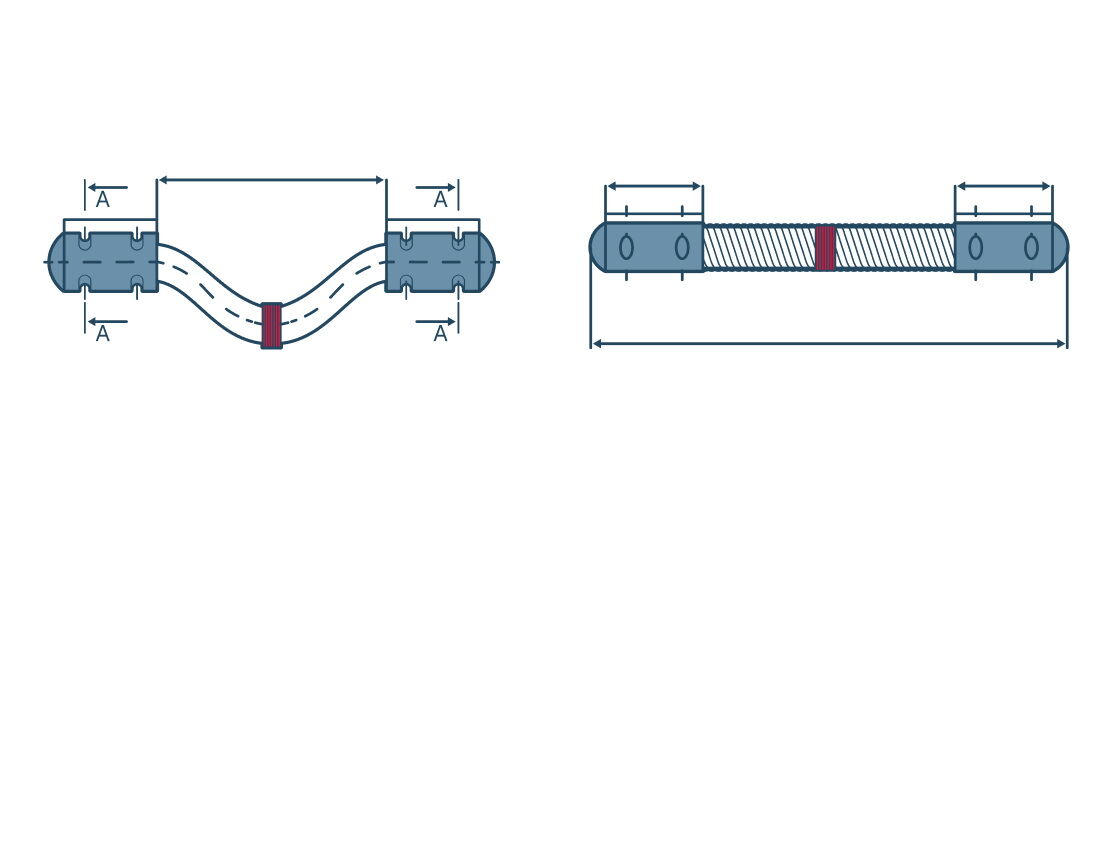
Применяется в рельсовых цепях на участках с электрической тягой. Соединитель изготавливается из медного провода сечением 50, 70, 95 и 120 мм² для участков с электротягой постоянного тока. Состоит из гибкого медного провода марки МГ, заваренного по концам в стальные манжеты фартучного типа. Соединитель фартучного типа РЭСФ является более совершенным модернизированным вариантом по сравнению с соединителями других типов.
Ключевые моменты
Устойчивость и прочность при механических воздействиях и после механических нагрузок для группы МС5 по ОСТ 32.146-2000 и соответствие требованиям ОСТ 32.146-2000.
Устойчивость при климатических воздействиях и после воздействия климатических факторов для группы К4 по ОСТ 32.146-2000 для условий транспортирования 5 (ОЖ4) по ГОСТ 15150-69 и соответствие требованиям ОСТ 32.146-2000.
Интенсивность отказов изделия должна быть не более 0,65 × 10⁻⁵ (1/ч).
Средний ресурс до капитального ремонта пути с установленными изделиями должен быть не менее 45 000 ч.
Установленный ресурс изделия до отказа должен быть не менее 9 000 ч при грузонапряжённости не более 120 млн т·км брутто на 1 км пути в год. Отказом считается внезапный выход из строя любого из комплектующих элементов, приводящий к потере работоспособности изделия и несоответствию требованиям ТУ.
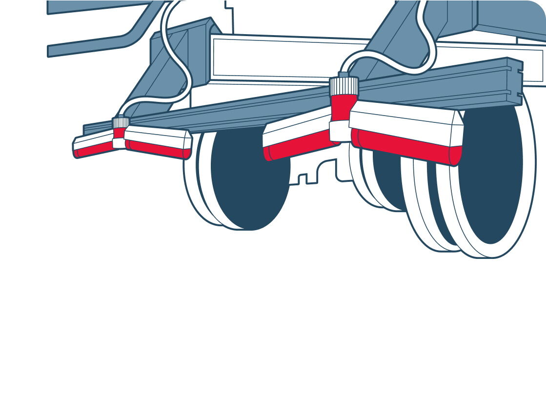
Термостабилизация (ДКС)
Описание принципа работы
Конструкция термостабилизатора позволяет разместить конденсаторную часть в условиях низкого подполья, а дисковое оребрение конденсатора обеспечивает максимальную эффективность функционирования ТСГ в условиях слабого обдува.
Эффекты от внедрения
Основная задача применения сезоннодействующих охлаждающих устройств — сохранение температурного режима вечномёрзлых грунтов на весь срок эксплуатации сооружения.
Ключевые моменты
Общее количество ТСГ — 484 шт.
Расположение ТСГ предусмотрено как с внешней стороны фундамента, так и в подполье, что позволяет предотвратить растепление грунтов, вызванное тепловым воздействием от сооружения, потеплением климата или иными тепловыми воздействиями, и даёт запас прочности к обеспечению несущей способности свайного основания.
Виртуальный консультант
Описание принципа работы
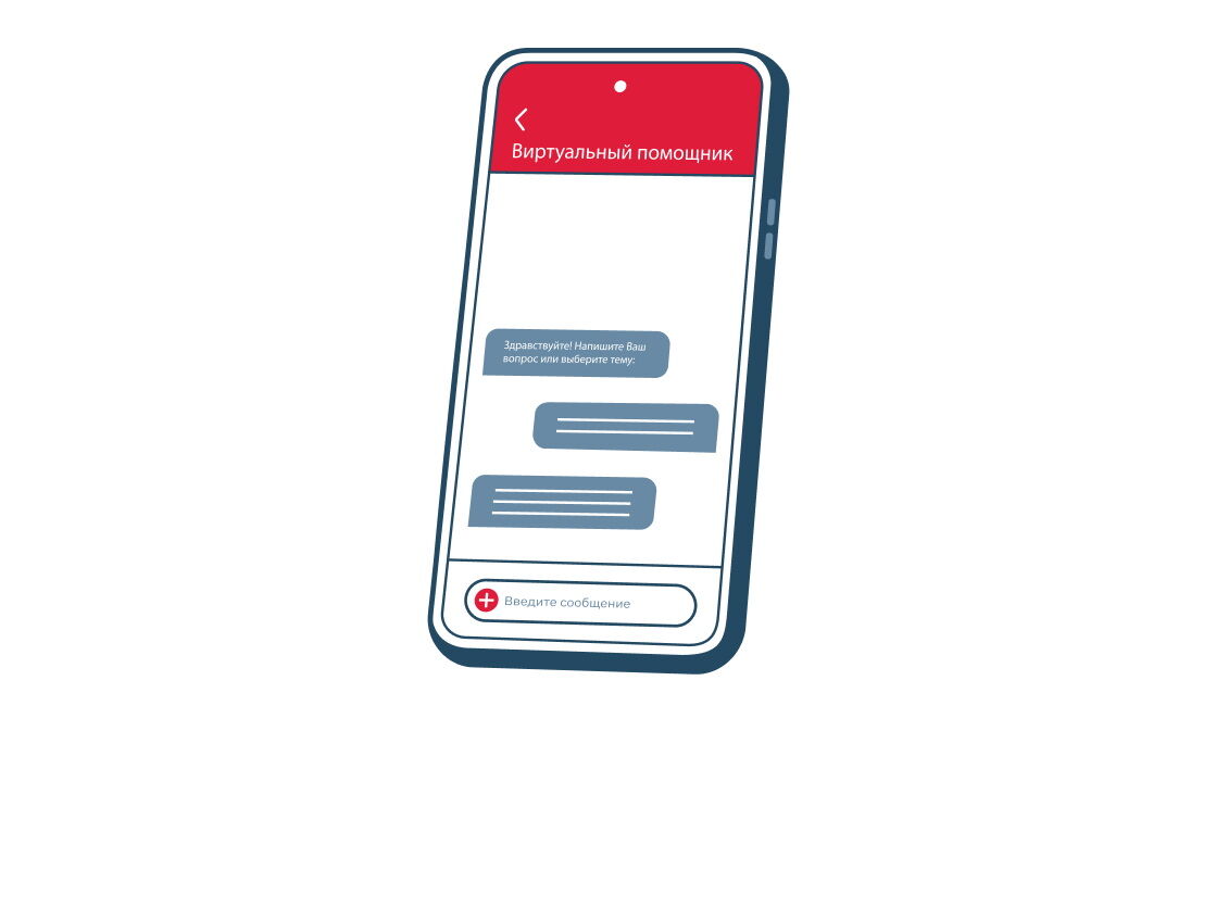
При отсутствии ответа чат-бот автоматически переадресует вопрос технологу, и обращение пользователя будет обработано в кратчайшие сроки. Заложенные алгоритмы решений обеспечивают сокращение временных затрат на получение консультационной помощи до одной минуты.
Сегодня наиболее востребованными сценариями по блоку управления трудовыми и финансовыми ресурсами являются консультации по полномочиям для учёта основных средств, налоговый учёт МПЗ, а также типовые ошибки при проводках по заказам контроллинга. Кроме того, популярностью пользуются запросы по привязке или определению на заводе материала или услуг, консультации по привязке контрагента в учётной системе, отпуску сотрудника, а также дистанционному обучению по охране труда и работе на высоте.
Эффекты от внедрения
Виртуальный консультант, внедряемый специалистами ИВЦ, позволяет за несколько минут эффективно решить сложный запрос.
В настоящее время пользователи чат-бота могут получить ответ по работе в 96 информационных системах холдинга более чем по 170 сценариям. Это небольшая часть всех запросов, решаемых технологами, однако цифровая система активно развивается.
Ключевые моменты
Полный переход на обработку обращений пользователей через автоматизированную систему (АС) «ВиКо» планируется в 2023–2024 годах. В связи с этим будет прекращена возможность создавать обращения через портал ЕСПП. АС «ВиКо» станет единственным способом получения технологической поддержки в режиме реального времени.
Применение аппаратного комплекса для обследования русловых участков рек (АПК)
Описание принципа работы
Комплекс используется для обследования русла, рельефа реки, определения наличия размывов и скоростей потока на поверхности и в толщине воды.
Эффекты от внедрения
Повышение качества и совершенствование технологии диагностики и мониторинга объектов инфраструктуры.
Снижение риска влияния человеческого фактора, цифровое представление результатов измерений.
Получение рельефа дна в районе мостового перехода и мониторинг развития местных размывов у опор.
Ключевые моменты
Проект обеспечивает выполнение требований, закреплённых нормативным документом федерального уровня «СП 79.13330.2014 Мосты и трубы. Правила обследования и испытаний» в части проведения гидрологических работ при обследовании мостовых переходов.
Техническая информация
Масштаб батиметрической съемки при обследовании русла и рельефа реки
1:300 — 1:500
Глубина обнаружения объектов на дне водных акваторий
20–30 м
Определение размывов в русле реки и около опор мостов
от 1 м²
Определение разрушения конструкции подводной части регуляционных сооружений с изменениями условий протекания водного потока
от 1 м²
Определение размывов тела или основания регуляционных сооружений
от 1 м²
Обследование поверхности подводной части опор мостов с изменениями условий протекания водного потока (разрушение бетона, вывалы кладки подводной части опор)
1 м²
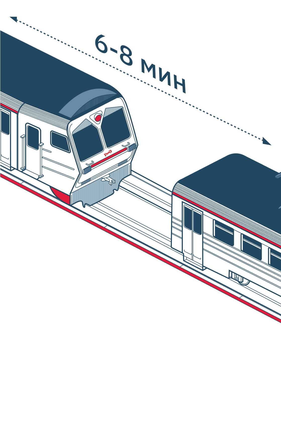
Система автоматической локомотивной сигнализации с подвижными блок-участками (АЛСО)
Описание принципа работы
АЛСО использует принцип подвижных блок-участков, что позволяет повысить пропускную способность на линии. Особенность системы в том, что движение поездов осуществляется только по сигналам локомотивных светофоров. Интервал между поездами регулируется исходя из фактической скорости каждого поезда на линии, а также скорости друг относительно друга. Регулирование движения поезда осуществляется в расчёте на координату хвоста впереди идущего поезда с учётом динамического защитного участка, в то время как в традиционных средствах автоблокировки регулирование осуществляется в расчёте на границу занятого блок-участка.
Эффекты от внедрения
Сокращение интервалов попутного следования поездов до 6 минут.
Повышение пропускной способности.
Отсутствие электромагнитных реле.
Исключение светофоров на перегонах с оптимизацией капитальных затрат при строительстве и оптимизацией эксплуатационных затрат при обслуживании.
Обеспечение минимального времени на восстановление графика движения поездов при сбоях.
Создание платформы для внедрения систем автоматического ведения поездов.
Ключевые моменты
Одним из ключевых факторов увеличения пропускной способности и грузопотока поездов является уменьшение интервалов попутного следования. Это становится возможным благодаря внедрению интервального регулирования движения. При реализации данного метода применяется отечественная система микропроцессорной автоблокировки АБТЦ-МШ с тональными рельсовыми цепями и централизованным размещением аппаратуры. Она предназначена для обеспечения безопасности движения поездов на перегонах и является частью инновационной системы интервального регулирования движения поездов с подвижными блок-участками.
Система имеет надежный алгоритм формирования модели поездной ситуации по сигналам от рельсовых цепей. При переходе от систем автоблокировки релейного типа к микропроцессорным значительно повышается надёжность, безопасность и энергоэффективность. Уменьшаются габариты используемого оборудования, а число выполняемых ими функций увеличивается.
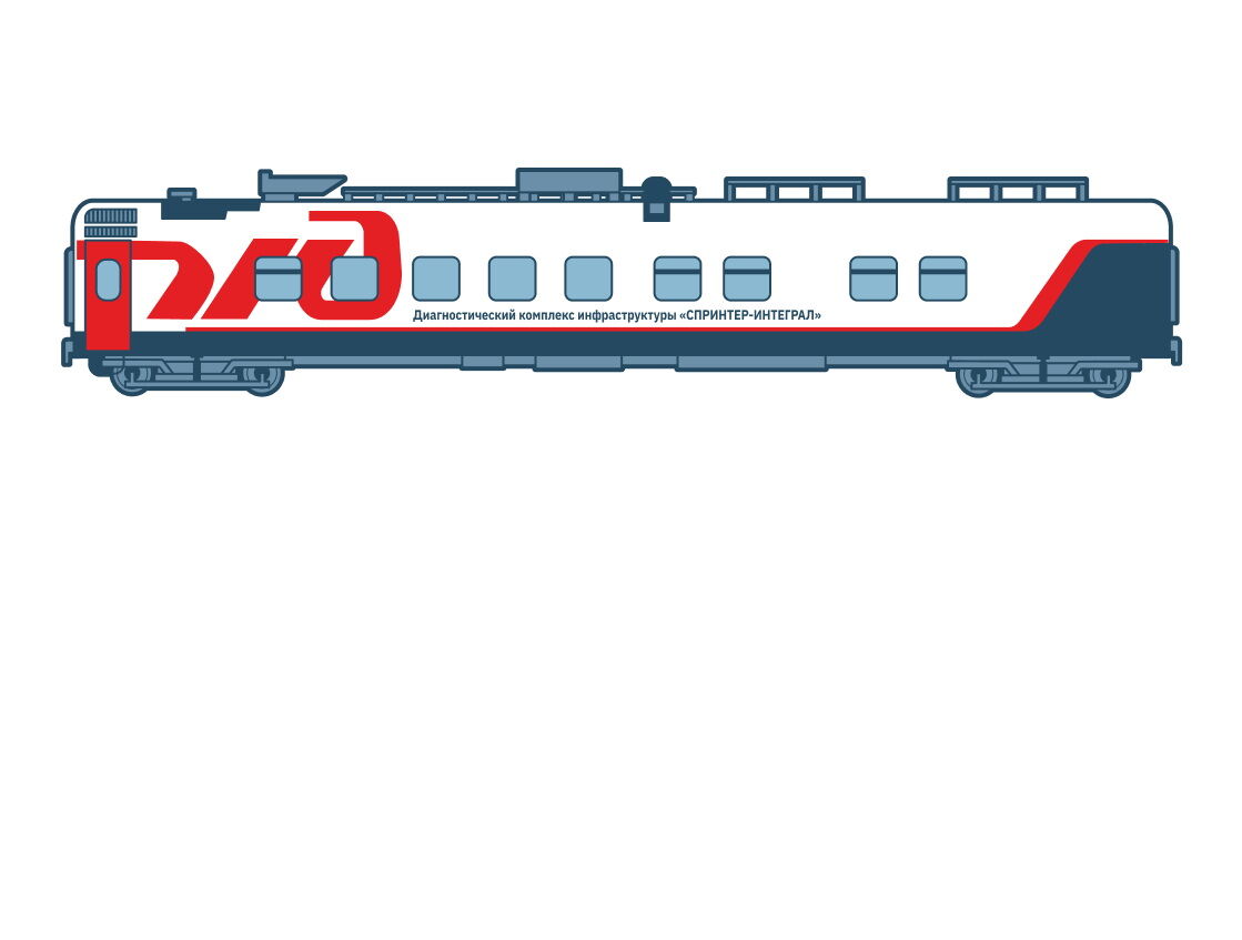
Диагностический комплекс инфраструктуры «СПРИНТЕР-ИНТЕГРАЛ»
Описание принципа работы
Сокращение парка диагностических средств за счёт перехода на комплексную технологию проверки состояния железнодорожного пути диагностическими комплексами инфраструктуры.
Эффекты от внедрения
Снижение количества МСД на 102 шт.
Снижение количества съёмных средств на 1 604 шт.
Увеличение выработки на 934 км на 1 МСД;
Снижение заказа локомотивов на 8 060 шт.
Ключевые моменты
Диагностический комплекс оснащён различными диагностическими и контролирующими системами третьего поколения, такими как: высокоскоростная ультразвуковая дефектоскопная система с многоканальным ультразвуковым дефектоскопом последнего поколения «ЭХО-КОМПЛЕКС-3» в комплекте со следящей, искательной системами и системой подачи воды; бесконтактная система измерения параметров геометрии рельсовой колеи «СОКОЛ-2»; система визуально-измерительного обнаружения дефектов элементов верхнего строения пути «СВОД-2» с автоматизированной расшифровкой данных контроля по 13 параметрам; многоканальная георадарная система МГС; система пространственного трёхмерного лазерного сканирования «Габарит-М»; система диагностики устройств автоматики и телемеханики, обеспечивающая контроль всех применяемых в настоящее время устройств; контроль параметров контактной сети.
Комплекс должен обеспечивать надёжную работу всех систем в светлое и тёмное время суток в диапазоне температур окружающего воздуха от −50 до +50 °C, при движении, в т. ч. при воздействии осадков в виде снега, дождя, града, тумана (при видимости от 10 м) и относительной влажности не более 95 % при 25 °С. Бесконтактные системы измерения должны обеспечивать контроль заданных параметров при наличии прямой видимости контролируемого объекта.
Наружное климатическое исполнение комплекса должно соответствовать макроклиматической зоне У категории 1 по ГОСТ 15150-69 «Машины, приборы и другие технические изделия. Исполнения для различных климатических районов. Категории, условия эксплуатации, хранения и транспортирования в части воздействия климатических факторов внешней среды». Находящееся внутри отапливаемых помещений ДКИ измерительное и диагностическое оборудование должно соответствовать по исполнению макроклиматической зоне У категории 4.1 по ГОСТ 15150-69 с диапазоном рабочей температуры от +1°С до +40 °С и относительной влажностью воздуха не более 80 % при температуре 25 °C. Системы и датчики, устанавливаемые вне кузова вагона, не должны реагировать на электромагнитные и ионизирующие излучения, присутствующие в контактной сети, и сами не должны являться источниками излучения. Конструкция систем и датчиков, в состав которых входят оптические и электронные элементы, должна обеспечивать их защиту от воздействия влаги, пыли, мелких механических частиц и атмосферных осадков. Системы и датчики должны производить измерения как в светлое, так и в тёмное время суток. Запотевание оптических элементов должно быть минимизировано.
Техническая информация
Линейная скорость движения
0–200 ± 2 км/ч
Погрешность в оценке пройденного пути
1 км ± 2 м
Температура окружающего воздуха
от −50 до +50 ± 1 °С
Температура рельсовых нитей
от −50 до +80 ± 2 °С
Привлечение научной организации СО РАН
Описание принципа работы
С целью проведения комплексных наблюдений за состоянием окружающей среды на территории проектируемых объектов на всех этапах строительства привлечена научная организация СО РАН.
Участок Восточно-Сибирской железной дороги и объект применения:
1. Железнодорожная инфраструктура на участке Лена-Восточная — Таксимо «Строительство двухпутной вставки на перегоне Северобайкальск — Блок-пост 1084»
2. Реконструкция мостов 1 и 2 путей на 5358 км ПК 10 участка Иркутск — Петровский Завод
3. Железнодорожная инфраструктура на участке Лена-Восточная — Таксимо «Строительство двухпутной вставки на перегоне Дельбичинда — Дабан»
4. Железнодорожная инфраструктура на участке Лена-Восточная — Таксимо «Строительство второго пути на перегоне Дабан — Гоуджекит»
5. Железнодорожная инфраструктура на участке Лена-Восточная — Таксимо «Строительство двухпутной вставки на перегоне Холодный — Кичера»
6. Реконструкция земляного полотна на 5435–5437 км участка Слюдянка — Улан-Удэ
7. Реконструкция земляного полотна на 5445–5447 км участка Слюдянка — Улан-Удэ
8. Реконструкция мостов 1 и 2 путей на 5359 км пк 4 участка Иркутск — Петровский Завод
9. Реконструкция мостов 1 и 2 путей на 5363 км пк 1 участка Иркутск — Петровский Завод
10. Реконструкция мостов 1 и 2 путей на 5385 км пк 2 участка Иркутск — Петровский Завод (полоса отвода).
Эффекты от внедрения
Высокая достоверность, оперативность и полнота сведений за счёт использования информации научной организации для своевременного принятия мер по исключению (минимизации) негативного воздействия на окружающую среду.
Диагностика устройств железнодорожной автоматики и телемеханики (ЖАТ)
Описание принципа работы
Диагностика параметров ЖАТ позволяет осуществлять:
- измерение временных и электрических параметров сигнала АЛСН
- регистрацию сигналов и измерение длины тональных рельсовых цепей
- измерение, декодирование и анализ электрических и геометрических параметров шлейфов САУТ
- измерение характеристик теплового тракта устройств КТСМ
- измерение параметров радиосвязи речевых информаторов КТСМ
Эффекты от внедрения
Повышение эксплуатационной надёжности систем железнодорожной автоматики и телемеханики при обеспечении допустимого уровня задержки поездов и приемлемой стоимости жизненного цикла на основе перераспределения ресурсов.
Ключевые моменты
Система контроля устройств автоматики и телемеханики должна обеспечить: измерение характеристик сигналов АЛСН (автоматическая локомотивная сигнализация непрерывного действия); измерение характеристик сигналов ТРЦ-3 (рельсовые цепи тональной частоты третьего поколения), ТРЦ-4 (рельсовые цепи тональной частоты четвёртого поколения); измерение характеристик сигналов АЛС-ЕН (автоматическая локомотивная сигнализация непрерывного действия для скоростного хода); измерение характеристик сигналов САУТ (система автоматического управления торможением поездов), САУТ-Ц (система автоматического управления торможением с централизованным размещением), САУТ-ЦМ (модернизированная система автоматического управления торможением с централизованным размещением путевых устройств); регистрацию остаточной разнополюсной намагниченности рельсов; проверку ориентации оптических систем приёмников напольных устройств КТСМ (комплекс технических средств мониторинга нагрева букс вагонов) на контрольную зону; контроль уровней настройки пороговых элементов КТСМ на заданный критерий аварийности путём имитации греющейся буксы и греющейся подступичной области подвижной единицы; видеоконтроль с высокой разрешающей способностью элементов устройств ЖАТ (железнодорожная автоматика и телемеханика) сигнальных точек, изолирующих стыков на станциях и перегонах, дроссельных перемычек, точек подключения шлейфов САУТ и ТРЦ и др.; тепловизионный контроль нагрева элементов путевых устройств железнодорожной автоматики (стрелочных приводов, дроссель-трансформаторов, дроссельных перемычек, стыковых соединителей, электротяговых отсосов и других элементов рельсовых цепей).
Геокомпозит МИАКОМ «ГЕО ДР 15_2М»
Описание принципа работы
Дренажный геокомпозит «ГЕО ДР» — это комбинированный дорожно-строительный материал, состоящий из ячеистого каркаса ромбовидной георешётки и внешнего геотекстильного слоя из нетканого фильтрационного полотна.
Эффекты от внедрения
Исключение проникновения загрязнённых вод с балластной призмы и земляного полотна в композитный лоток и далее на очистные сооружения поверхностных сточных вод.
Геокомпозит «ГЕО ДР» отличается высокими показателями прочности, жёсткости и надёжности, дренажные георешётки материала имеют отличную водопропускную способность и повышенный коэффициент трения, за счёт чего обеспечивается эффективность и долговечность применения этого материала.
Ключевые моменты
Локации применения: железнодорожная инфраструктура на участке Лена-Восточная — Таксимо Восточно-Сибирской железной дороги.
Наименование объекта: строительство двухпутной вставки на перегоне Северобайкальск — Блок-пост 1 084 км (земляное полотно).
Диагностика геометрии рельсовой колеи
Описание принципа работы
Вагоны-путеизмерители в автоматическом режиме контролируют параметры рельсовой колеи: ширину колеи (сужение и уширение), положение рельсовых нитей по уровню (перекосы и плавные отклонения по уровню), просадки рельсовых нитей, положение пути в плане. Исходя из целей наиболее рационального определения видов и сроков выполнения работ по устранению и предупреждению появления отступлений от норм содержания рельсовой колеи при условии обеспечения безопасности движения поездов, оценка отступлений от номинальных значений контролируемых параметров производится по четырём степеням их величин, регламентированным в зависимости от установленных скоростей движения поездов: чем выше установленные скорости движения, тем меньше регламентированные величины степеней отступлений (или амплитуда).
Ключевые моменты
Контроль состояния геометрии рельсовой колеи и рельсов осуществляется по шести параметрам: взаимное расположение обеих рельсовых нитей по высоте (уровень), ширина рельсовой колеи, просадки, углы в плане, продольный профиль пути, уклон продольного профиля пути.
Дополнительные параметры геометрии рельсовой колеи осуществляются по 16 параметрам: длинные неровности в плане и профиле, подуклонка рельсов, вертикальный износ рельсов, боковой износ рельсов, износ головки рельсов под углом 45°, приведённый износ головки рельсов, линейная скорость движения, пройденный путь, температура окружающего воздуха, температура рельсовых нитей, наклон поверхности катания рельсов, распознавание рельсовых пересечений, диапазон длин волн, позиционирование в железнодорожной системе координат, позиционирование в системе координат с использованием поправок референтных станций или без него.
Технология включает бесконтактную система контроля основных и дополнительных параметров геометрии рельсовой колеи и рельсов, а также контактную систему контроля параметров геометрии рельсовой колеи. Обе системы должны функционировать независимо друг от друга.
В части основных параметров геометрии рельсовой колеи, независимо от используемой системы (контактной или бесконтактной), должны быть реализованы контроль и оценка следующих параметров: уровень; положение рельсовых нитей в плане (рихтовка); положение рельсовых нитей в профиле (просадка); ширина колеи (шаблон).
В части дополнительных параметров геометрии рельсовой колеи должны быть реализованы контроль и оценка следующих параметров: продольный профиль пути; длинные неровности пути в плане и профиле; короткие неровности на поверхности катания рельсов; температура рельсовых нитей.
Контроль и оценка параметров поперечного профиля рельсов (износ головок рельсов, наклон поверхности катания, подуклонка, эквивалентная конусность) реализуются бесконтактной системой измерения.
Применение лазерного сканирования для создания цифровых моделей искусственных сооружений
Описание принципа работы
Для создания цифровых моделей искусственных сооружений.
Эффекты от внедрения
Обследование в условиях недостаточного освещения рабочей зоны (исключение человеческого фактора при работе в темноте).
Исключение заявок на первичное окно и мотовоз для осмотра конструкций.
Очертание и контроль деформаций в любом сечении.
Съёмка ранее не обследованных конструкций (выработки, штольни и т. д.).
Габаритный прогон любых негабаритных очертаний с учётом выноса.
Создание цифрового двойника.
Ключевые моменты
Проект обеспечивает выполнение требований нормативного документа федерального уровня СП 79.13330.2014 «Мосты и трубы. Правила обследования и испытаний» в части проведения геодезических работ и наблюдений. Высокоточная лазерная съёмка несущих конструкций искусственных сооружений. Своевременное выявление деформаций конструкций. Снижение риска нарушения безопасности движения поездов и потери актива. Формирование облака точек для создания модели цифрового двойника сооружения.
Для автоматической сшивки изображения используется инерциальная система.
Технология реализует возможность управления на самом приборе и через мобильное приложение.
Присутствует функция фильтрации движущихся объектов.
Техническая информация
Время на круговой скан с фото
2 мин.
Максимальная дальность измерений
120 м
Точность измерения расстояний
1,7 мм + 10 ppm
Скорость измерений
2 млн точек в секунду
Поле зрения (горизонтальное/вертикальное)
360°/300°
Количество встроенных HDR-фотокамер
3 шт.
Температура эксплуатации
то −10 до +40 °С
Применение электронного бланка накладной Сахалин (ДТЦФТО)
Описание принципа работы
С июня 2023 года перевозка грузов и порожних вагонов с дальневосточной магистрали с участием паромной переправы Ванино — Холмск — Ванино оформляется в электронном виде. Ранее, чтобы отправить груз через переправу, клиентам ОАО «РЖД» необходимо было оформлять накладную по форме ГУ-28 только на бумаге.
Эффекты от внедрения
Оформление и раскредитование железнодорожной накладной требовало личного присутствия клиента на железнодорожной станции. Перевозки без участия парома оформляются в электронном виде по технологии «Автоагент», что существенно снижает временные потери клиентов.
Ключевые моменты
Форма накладной ГУ-28 регламентирована Правилами перевозок грузов от 1956 года с последними изменениями от 1984 года. Бумажный бланк ГУ-28 было предложено заменить на универсальный бланк ГУ-27уВЦ, оформляемый в электронном виде.
Автомашинист пригородных электропоездов УСАВП
Описание принципа работы
Унифицированная система автоматизированного ведения (УСАВП) предназначена для обеспечения автоматического управления режимами тяги и торможения электропоездов постоянного и переменного тока. Она позволяет с высокой точностью выполнять график движения при оптимальном расходе электроэнергии на тягу и облегчает работу машинистов. Система автоведения пригородных электропоездов выполнена на базе микропроцессорных технологий и представляет собой программно-аппаратный комплекс, обеспечивающий автоматизированное управление электропоездом.
Эффекты от внедрения
Сокращение расхода электроэнергии от 2 до 10 % (в зависимости от условий эксплуатации).
Повышение уровня безопасности движения.
Информационная поддержка машиниста в ночные и утренние часы, а также в условиях плохой видимости (снег, дождь, туман).
Снижение отрицательного влияния сложных поездных ситуаций на психофизиологическое состояние машиниста.
Сокращение сроков обучения машинистов и освоения малоопытными машинистами энергооптимальных режимов ведения поезда.
Повышение качества обслуживания пассажиров за счёт точного соблюдения расписания, гарантированного объявления названий остановочных пунктов и другой социальной информации.
Ключевые моменты
Автоматизированное ведение поезда с применением математически обоснованного энергосберегающего алгоритма, учитывающего профиль пути, постоянные и временные ограничения скорости, требующие особого режима движения путевые объекты.
Торможение под запрещающие и требующие ограничения скорости сигналы светофоров с точностью до 50 м, а также торможение для выполнения постоянных и временных ограничений скорости.
Оповещение пассажиров электропоезда в автоматическом режиме об остановках и маршруте следования.
Режим подсказок при ручном управлении.
Режим «Автоведение» освобождает машиниста от многих рутинных операций, связанных с управлением электропоездом. Действия машиниста сводятся к контролю остановочных пунктов. При этом система автоведения выдаёт голосовые сообщения о приближающихся путевых объектах, об ограничениях скорости и об изменениях сигналов светофоров.
Автоматизированное рабочее место подготовки данных позволяет рассчитывать энергооптимальную траекторию движения поезда для управляющей бортовой программы системы автоведения, а также проводить корректировку этой программы при смене расписания. Техническая новизна систем автоведения для электропоездов подтверждается полученными патентами и свидетельствами о регистрации программного обеспечения.
Техническая информация
Напряжение питания
+50 или +110 В
Внутренний процессор (производительность)
500 МГц
Внешняя Flash-память
64 Мб
Общая масса системы с монтажным комплектом
38,4 кг